Infiniti M35/M45 Y50. Manual — part 338

TROUBLE DIAGNOSIS FOR SYMPTOMS
BRC-53
[VDC/TCS/ABS]
C
D
E
G
H
I
J
K
L
M
A
B
BRC
Vehicle Jerks During VDC/TCS/ABS Control
NFS000R9
1.
SYMPTOM CHECK
Check if the vehicle jerks during VDC/TCS/ABS control.
OK or NG
OK
>> Normal.
NG
>> GO TO 2.
2.
CHECK SELF-DIAGNOSIS RESULTS
Perform self-diagnostic of ABS actuator and electric unit (control unit).
Are self-diagnosis results indicated?
YES
>> Check corresponding items, make repairs, and perform ABS actuator and electric unit (control
unit) self-diagnosis.
NO
>> GO TO 3.
3.
CHECK CONNECTOR
●
Turn ignition switch OFF and disconnect ABS actuator and electric unit (control unit) connector and check
terminal for deformation, disconnection, looseness, etc.
●
Securely connect connectors and perform ABS actuator and electric unit (control unit) self-diagnosis.
Are self-diagnosis results indicated?
YES
>> If poor contact, damage, open or short circuit of connector terminal is found, repair or replace.
NO
>> GO TO 4.
4.
CHECK ECM AND TCM SELF-DIAGNOSIS RESULTS
Perform ECM and TCM self-diagnosis.
Are self-diagnosis results indicated?
YES
>> Check the corresponding items.
●
(VK45DE).
●
TCM: Refer to
NO
>> Replace ABS actuator and electric unit (control unit).
BRC-54
[VDC/TCS/ABS]
WHEEL SENSOR
WHEEL SENSOR
PFP:47910
Removal and Installation
NFS000RA
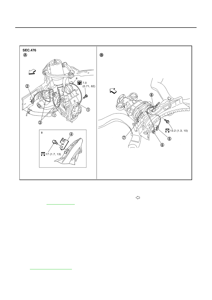
COMPONENT
NOTE:
The above figure (front side) shows left side. Right side is the mirror image.
REMOVAL
Pay attention to the following when removing sensor.
CAUTION:
●
Do not twist sensor harness as much as possible, when removing it. Pull sensors out without pull-
ing on sensor harness.
●
Take care to avoid damaging sensor edges or rotor teeth. Remove wheel sensor first before
removing front or rear wheel hub. This is to avoid damage to sensor wiring and loss of sensor
function.
INSTALLATION
Pay attention to the following when installing wheel sensor. Tighten installation bolts to the specified torques.
Refer to
.
1.
Front LH wheel sensor
2.
Front LH wheel sensor connector
3.
Clamp
4.
Bracket
5.
Rear RH wheel sensor connector
6.
Rear LH wheel sensor connector
7.
Rear LH wheel sensor
8.
Rear RH wheel sensor
A.
Front side
B.
Rear side
: Front
Refer to GI section
for symbol marks in the figure.
SFIA2723J
WHEEL SENSOR
BRC-55
[VDC/TCS/ABS]
C
D
E
G
H
I
J
K
L
M
A
B
BRC
●
When installing, make sure there is no foreign material such as iron chips on and in the mounting hole of
the wheel sensor. Make sure no foreign material has been caught in the sensor rotor. Remove any foreign
material and clean the mount.
●
When installing wheel sensor, be sure to press rubber grommets in until they lock at locations shown
above in the figure. When installed, harness must not be twisted.
BRC-56
[VDC/TCS/ABS]
SENSOR ROTOR
SENSOR ROTOR
PFP:47970
Removal and Installation
NFS000RB
REMOVAL
CAUTION:
Do not reuse sensor rotor.
Front
●
Sensor rotor cannot be disassembled. Remove the sensor rotor together with hub bearing assembly.
Refer to
.
Rear
●
Follow the procedure below to remove rear sensor rotor.
–
Remove side flange. Refer to
–
Using a bearing replacer (suitable tool) and puller (suitable tool), remove sensor rotor from side flange.
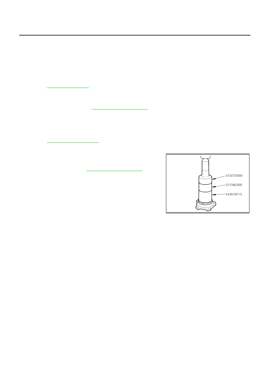
INSTALLATION
Front
●
Sensor rotor cannot be disassembled. Remove the sensor rotor together with hub bearing assembly.
Refer to
Rear
●
Follow the procedure below to install rear sensor rotor.
–
Using a drift (SST), press rear sensor rotor onto side flange.
–
Install side flange. Refer to
SFIA2040J
Нет комментариевНе стесняйтесь поделиться с нами вашим ценным мнением.
Текст