Infiniti M35/M45 Y50. Manual — part 376

LANE DEPARTURE WARNING SYSTEM
DI-87
C
D
E
F
G
H
I
J
L
M
A
B
DI
TKWT5288E

DI-88
LANE DEPARTURE WARNING SYSTEM
Terminals and Reference Value for LDW Camera Unit
NKS003VL
NOTE:
*: Perform “ACTIVE TEST” with CONSULT-II. Refer to
CONSULT-II Function (LDW)
NKS003VM
DESCRIPTION
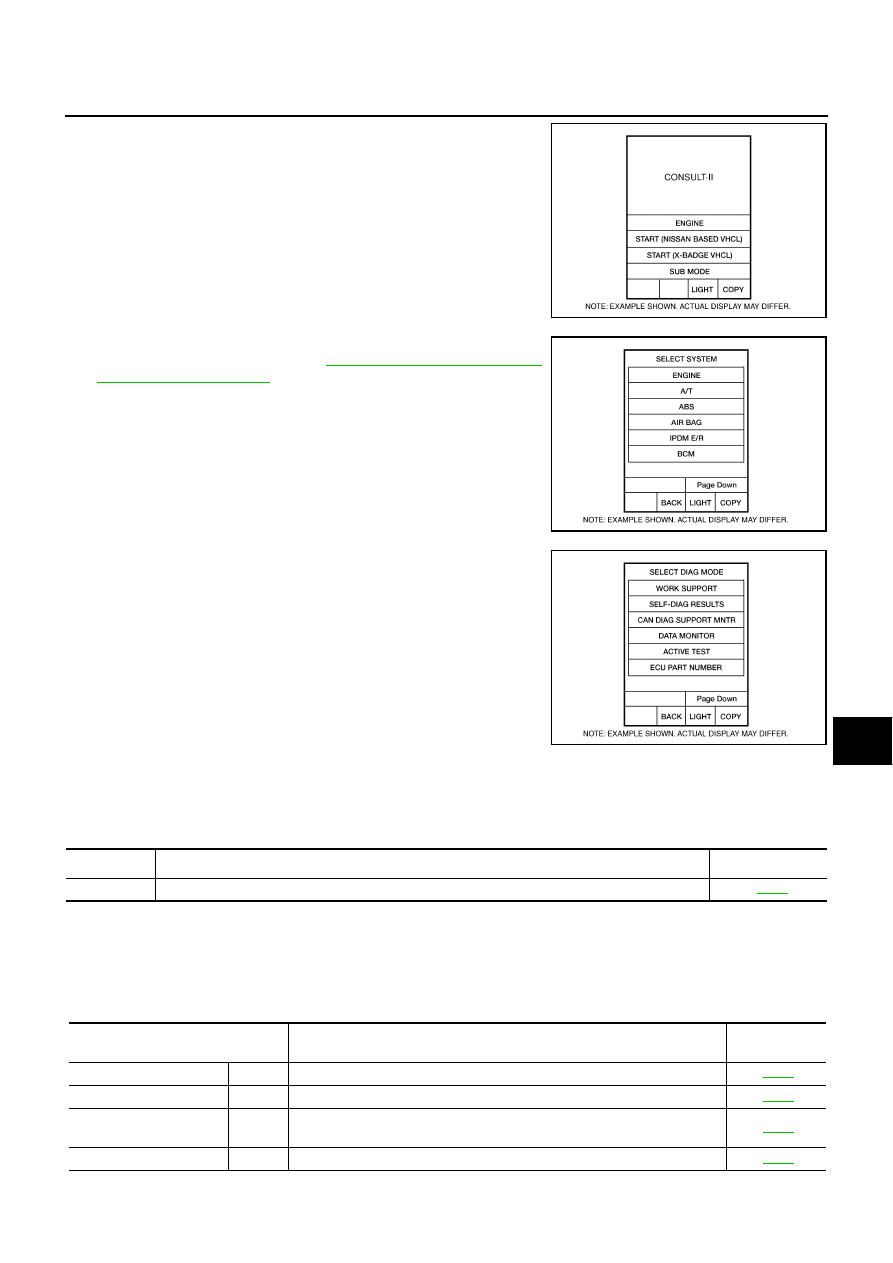
CONSULT-II can display each diagnostic item using the diagnostic test modes shown following.
CONSULT-II BASIC OPERATION
CAUTION:
If CONSULT-II is used with no connection of CONSULT-II CONVERTER, malfunctions might be
detected in self-diagnosis depending on control unit which carry out CAN communication.
1.
With the ignition switch OFF, connect CONSULT-II and CON-
SULT-II CONVERTER to the data link connector, and then turn
ignition switch ON.
Terminal
No.
Wire
color
Item
Condition
Reference value
(Approx.)
Ignition
switch
Operation or condition
1
B/R
Ignition switch ON or START
ON
—
Battery voltage
3
R/W
LDW chime
ON
LDW chime
Activated
*
0 V
Not activated
12 V
4
V
System ON indicator
ON
LDW system
ON
0 V
OFF
12 V
5
P
CAN–L
—
—
—
6
B
Ground
ON
—
0 V
8
G/W
LDW indicator lamp
ON
LDW indicator lamp
Illuminated
*
0 V
Turned OFF
12 V
9
GR
LDW switch
ON
LDW switch
Pushed
0 V
Released
5 V
10
L
CAN–H
—
—
—
12
B
Ground
ON
—
0 V
System
Diagnosis mode
Description
Reference
page
LDW
WORK SUPPORT
Displays causes of automatic cancellation of the LDW system.
SELF-DIAG RESULTS
Displays malfunctioning system memorized in LDW camera unit.
DATA MONITOR
Displays real-time input/output data of LDW camera unit.
CAN DIAG SUPPORT MNTR
Displays the results of transmit/receive diagnosis of CAN communication.
ACTIVE TEST
Enables operation check of electrical loads by sending driving signal to them.
ECU PART NUMBER
Displays part number of LDW camera unit.
—
SKIB3794E
LANE DEPARTURE WARNING SYSTEM
DI-89
C
D
E
F
G
H
I
J
L
M
A
B
DI
2.
Touch “START (NISSAN BASED VHCL)”.
3.
Touch “LDW” on “SELECT SYSTEM” screen.
If “LDW” is not displayed, go to
.
4.
Touch any field, “WORK SUPPORT”, “SELF-DIAG RESULTS”,
“DATA MONITOR”, “CAN DIAG SUPPORT MNTR”, “ACTIVE
TEST” or “ECU PART NUMBER”, on selection screen.
WORK SUPPORT
Operation Procedure
Touch “WORK SUPPORT” on “SELECT DIAG MODE” screen.
Display Item List
SELF-DIAG RESULTS
Operation Procedure
1.
Touch “SELF-DIAG RESULTS” on “SELECT DIAG MODE” screen.
2.
See the displayed result of self-diagnosis.
Display Item List
BCIA0029E
BCIA0030E
BCIA0031E
Operation
Function
Reference page
AUTO AIM
LDW camera unit calculates dislocation of the camera. Adjustment direction is displayed.
Display item [Code]
Malfunction is detected when...
Reference
page
CAMERA UNIT MALF
[C1B00]
LDW camera unit internal malfunction
CAM AIMING INCMP
[C1B01]
LDW camera aiming is not adjusted.
VHCL SPD DATA MALF
[C1B02]
LDW camera unit detected different vehicle speed signal from TCM and
ABS actuator and electric unit (control unit).
ABNRML TEMP DETECT
[C1B03]
Temperature around LDW camera unit is excessively high.

DI-90
LANE DEPARTURE WARNING SYSTEM
NOTE:
●
When a DTC is detected, the LDW system dose not operate.
●
When the DTC except “ABNRML TEMP DETECT [C1B03] ” is detected, the LDW indicator lamp turns ON.
●
When the DTC “ABNRML TEMP DETECT [C1B03] ” is detected, the LDW system ON indicator lamp blinks.
DATA MONITOR
Operation Procedure
1.
Touch “DATA MONITOR” on “SELECT DIAG MODE” screen.
2.
Touch any of “ALL SIGNALS” and “SELECTION FROM MENU” on selection screen.
3.
Touch “START”.
4.
Display the data monitor.
5.
If necessary, touch “COPY” in turn, and print data.
Display Item List
CAN COMM CIRCUIT
[U1000]
LDW camera unit detected CAN communication malfunction.
CONTROL UNIT (CAN)
[U1010]
LDW camera unit detected internal CAN communication circuit malfunction.
Display item [Code]
Malfunction is detected when...
Reference
page
Monitored Item [unit]
Description
MAIN SW
[ON/OFF]
Displays [ON/OFF] status as judged from LDW switch signal.
SW ON LAMP
[ON/OFF]
Displays [ON/OFF] status of LDW system ON indicator signal output.
INDICATE LAMP
[ON/OFF]
Displays [ON/OFF] status of LDW indicator signal output.
BUZZER OUTPUT
[ON/OFF]
Displays [ON/OFF] status of LDW chime operation signal output.
LDW INACCURAT
[ON/OFF]
Displays LDW camera unit status.
VHCL SPD SE
[km/h] or [mph]
Displays vehicle speed calculated by LDW camera unit through CAN communication [ABS
actuator and electric unit (control unit) transmits wheel sensor signal through CAN communi-
cation].
VHCL SPD AT
[km/h] or [mph]
Displays vehicle speed calculated from A/T vehicle speed sensor by LDW camera unit through
CAN communication (TCM transmits A/T vehicle speed sensor signal through CAN communi-
cation).
TURN SIGNAL
[OFF/LH/RH]
Displays “Turn signal” status, determined from BCM through CAN communication.
LANE DETCT LH
[ON/OFF]
Displays left lane marker is detected.
LANE DETCT RH
[ON/OFF]
Displays right lane marker is detected.
CROSS LANE LH
[ON/OFF]
Displays vehicle is crossing left lane.
CROSS LANE RH
[ON/OFF]
Displays vehicle is crossing right lane.
WARN LANE LH
[ON/OFF]
Displays warning for left lane.
WARN LANE RH
[ON/OFF]
Displays warning for right lane.
VALID POS LH
[VLD/INVLD]
Displays lateral position for left lane marker is valid.
VALID POS RH
[VLD/INVLD]
Displays lateral position for right lane marker is valid.
AIMING DONE
[OK/NG]
Displays camera aiming done.
AIMING RESULT
[OK/NOK]
Displays camera aiming result.
FCTRY AIM YAW
[deg]
Displays camera unit installation condition.
FCTRY AIM ROL
[deg]
Displays camera unit installation condition.
FCTRY AIM PIT
[deg]
Displays camera unit installation condition.
XOFFSET
[pixel]
Displays camera unit installation condition.
Нет комментариевНе стесняйтесь поделиться с нами вашим ценным мнением.
Текст