Infiniti M35/M45 Y50. Manual — part 374
LANE DEPARTURE WARNING SYSTEM
DI-79
C
D
E
F
G
H
I
J
L
M
A
B
DI
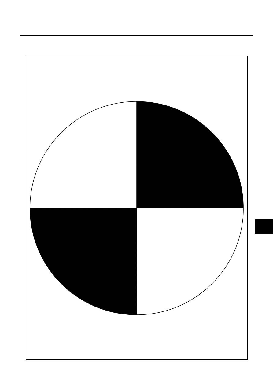
Target
NOTE:
Enlarge this page to 122% size and print it out.
PGIA0105J
DI-80
LANE DEPARTURE WARNING SYSTEM
Target Setting
CAUTION:
●
Perform this operation in a horizontal position where there is a clear view for 5 m (16.4 ft) forward
and 3 m (9.84 ft) wide.
●
Place the target at a well-lighted location. (Poor lighting may make it hard to adjust.)
●
The target may not be detected when there is a light source within 1.5 m (4.92 ft) from either side
and within 1 m (3.28 ft) upward/downward from the target.
●
Make sure location of the sun. (Sunlight should not shine directly on front of the vehicle.)
●
The target may not be detected when there is the same pattern of black and white as the target
when the pattern is within 1 m (3.28 ft) from either side and upward/downward position from the
target. (It is desirable that the vehicle is positioned on the opposite side of a single-color wall.)
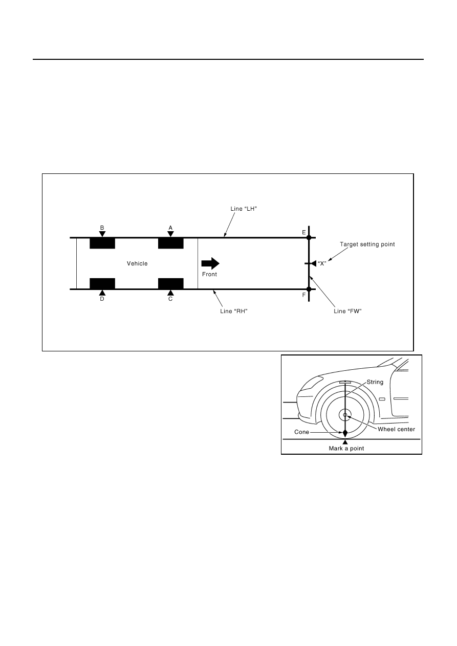
1.
Mark a point at the center of lateral surface of each wheels (“A”,
“B”, “C” and “D”).
NOTE:
Dangle a string with a cone from the fender so as to pass
through the center of wheel, and then mark a point at the center
of lateral surface of wheels.
2.
Draw a line passing through points “A” and “B” on the left side of
vehicle (line “LH”).
NOTE:
Approximately 4 m (13.12 ft) or more from the forward end of
vehicle.
3.
Mark points on the line “LH”, at the positions 3850 mm (151.57 in) from the point “A” (“E”).
4.
Draw a line passing through the points “C” and “D” on the right side of vehicle as with the step 2 (line
“RH”).
NOTE:
Approximately 4 m (13.12 ft) or more from the forward end of vehicle.
5.
Mark points on the line “RH”, at the positions 3850 mm (151.57 in) from the point “C” (“F”).
6.
Draw a line passing through the points “E” and “F” (line “FW”).
PKIB4694E
PKIB7667E
LANE DEPARTURE WARNING SYSTEM
DI-81
C
D
E
F
G
H
I
J
L
M
A
B
DI
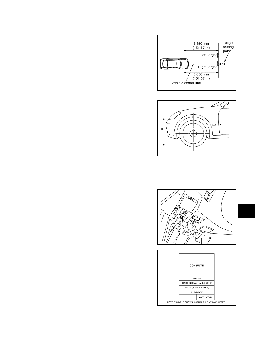
7.
Mark point at the center of the point “E” and “F”, on the line
“FW”.
CAUTION:
Make sure that “E” through “X” is equal to “F” through “X”.
8.
Position the center of the right target to the point of “X”.
VEHICLE HEIGHT CHECK
Measure the wheel arch height. And calculate “Dh”.
NOTE:
“Dh” may be calculated as a minus value.
AIMING ADJUSTMENT
Operation Procedure
CAUTION:
●
Perform the adjustment under unloaded vehicle condition.
●
LDW indicator is turned off after the removal/installation, and blinks after replacement.
1.
With the ignition switch OFF, connect CONSULT-II and CON-
SULT-II CONVERTER to the data link connector, and then turn
ignition switch ON.
2.
Start the engine, wait for at least 10 seconds, and touch “START
(NISSAN BASED VHCL)”.
PKIB7668E
Dh [mm] = (Hfl + Hfr)
÷
2
−
731
where,
Hfl: Front left wheel arch height [mm]
Hfr: Front right wheel arch height [mm]
PKIB7669E
SKIB3794E
BCIA0029E
DI-82
LANE DEPARTURE WARNING SYSTEM
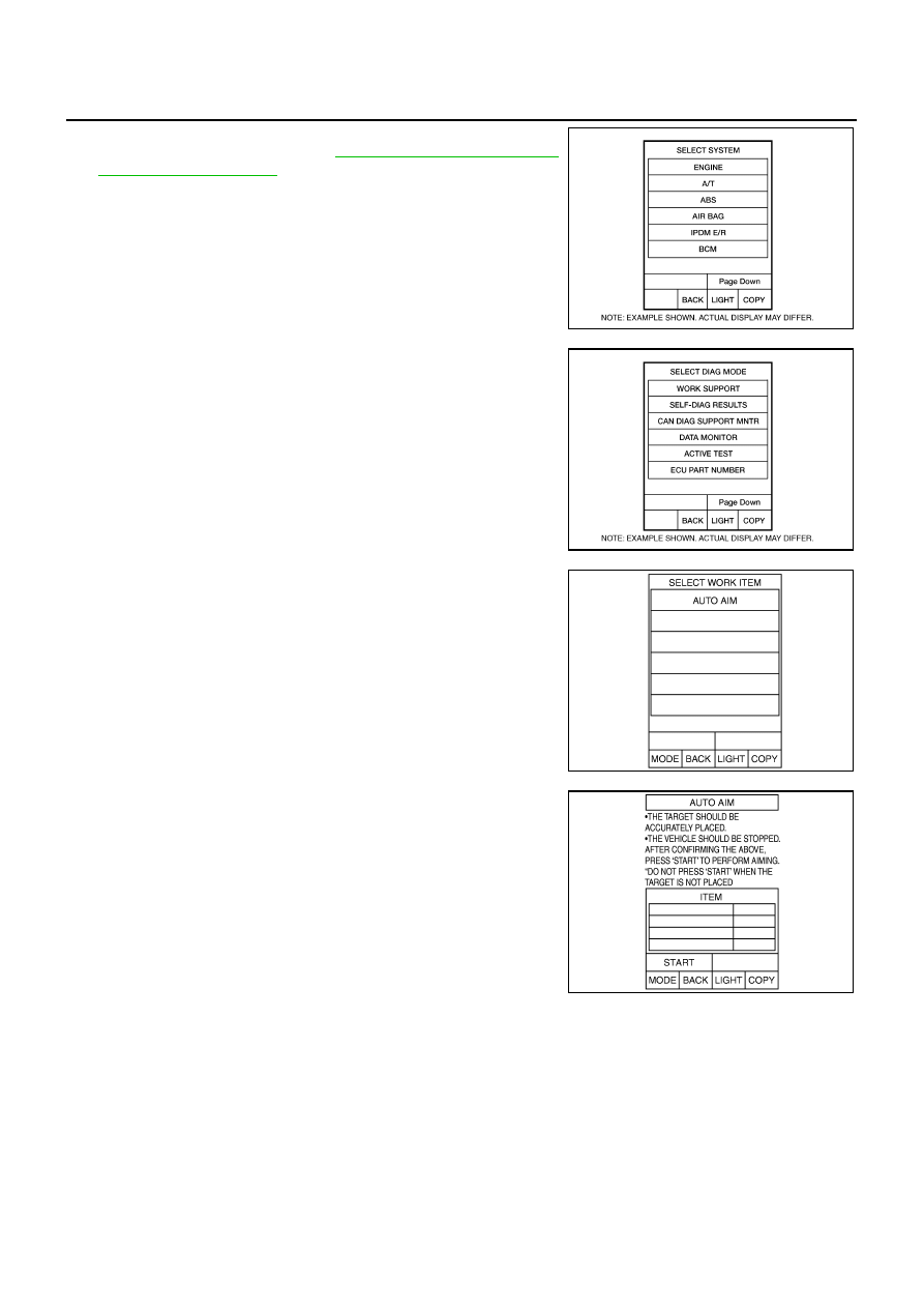
3.
Touch “LDW”.
If “LDW” is not displayed, go to
4.
Touch “WORK SUPPORT”.
5.
Touch “AUTO AIM”.
6.
The target should be accurately placed.
The vehicle should be stopped.
After confirming the above, touch “START” to perform aiming.
CAUTION:
Never touch “START” when the target is not placed.
BCIA0030E
BCIA0031E
PKIB4696E
SKIB3146E
Нет комментариевНе стесняйтесь поделиться с нами вашим ценным мнением.
Текст