Infiniti M35/M45 Y50. Manual — part 950
OIL PUMP
LU-31
[VK45DE]
C
D
E
F
G
H
I
J
K
L
M
A
LU
OIL PUMP
PFP:15010
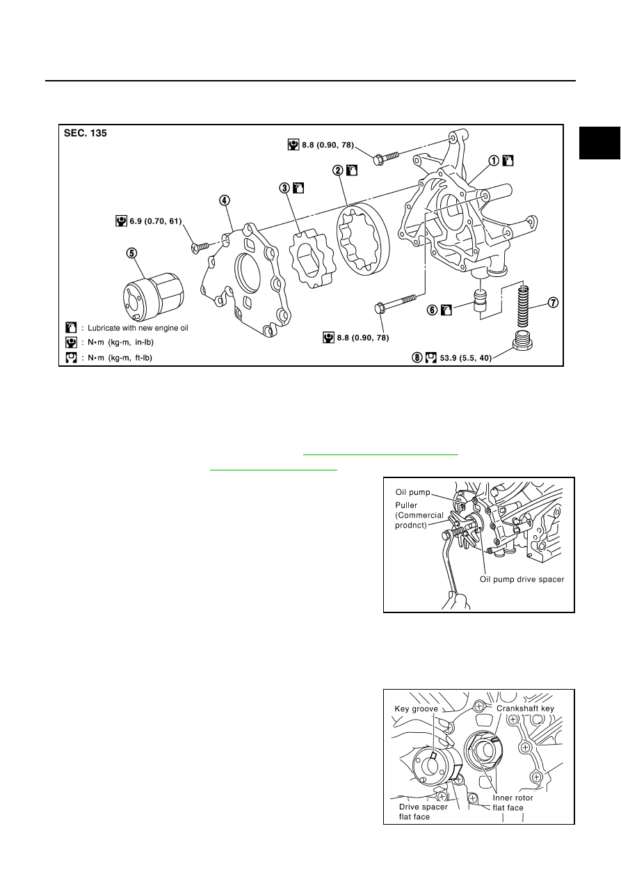
Components
NBS004QF
Removal and Installation
NBS004QG
REMOVAL
1.
Remove engine assembly from vehicle. Refer to
2.
3.
Remove oil pump drive spacer.
●
Set bolts in the two bolt holes [M6
×
pitch 1.0 mm (0.04 in)] on
the front surface. Using suitable puller, pull oil pump drive
spacer off from crankshaft.
NOTE:
The dimension between the centers of the two bolt holes is 33
mm (1.30 in).
In the figure, a commercial steering puller is used.
4.
Remove oil pump.
INSTALLATION
1.
Install the oil pump.
2.
Install oil pump drive spacer as follows:
a.
Insert oil pump drive spacer according to the directions of crank-
shaft key and the two flat surfaces of oil pump inner rotor.
●
If the positional relationship does not allow the insertion,
rotate oil pump inner rotor with a finger to allow spacer.
b.
After confirming that the position of each part is in correct condi-
tion to allow for spacer, force fit spacer by lightly tapping with
plastic hammer until it contacts and does not go further.
1.
Oil pump body
2.
Oil pump outer rotor
3.
Oil pump inner rotor
4.
Oil pump cover
5.
Oil pump drive spacer
6.
Regulator valve
7.
Regulator valve spring
8.
Regulator valve plug
PBIC1592E
PBIC0054E
PBIC0058E
LU-32
[VK45DE]
OIL PUMP
3.
Install in the reverse order of removal after this step.
INSPECTION AFTER INSTALLATION
1.
Check the engine oil level. Refer to
.
2.
Start engine, and check there is no leak of engine oil.
3.
Stop engine and wait for 15 minutes.
4.
Check the engine oil level and adjust engine oil. Refer to
.
Disassembly and Assembly
NBS004QH
DISASSEMBLY
1.
Remove oil pump cover.
2.
Remove oil pump inner rotor and oil pump outer rotor from oil pump body.
3.
After removing regulator valve plug, remove regulator valve spring and regulator valve.
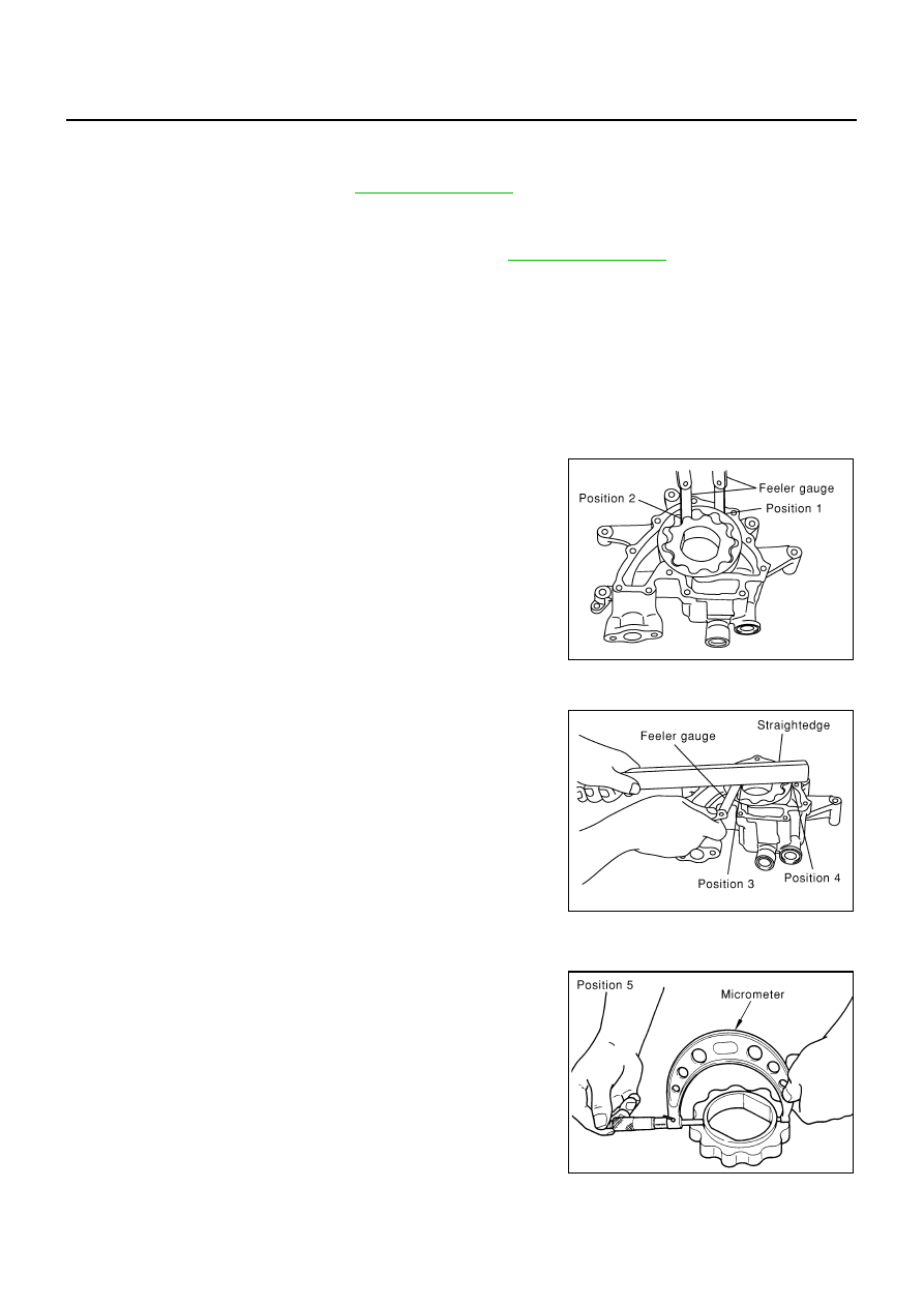
INSPECTION AFTER DISASSEMBLY
Oil Pump Clearance
●
Measure the clearance with feeler gauge.
–
Clearance between oil pump outer rotor and oil pump body
(Position 1)
–
Tip clearance between oil pump inner rotor and oil pump outer
rotor (Position 2)
–
If out of the standard, replace inner rotor and outer rotor.
●
Measure the clearance with feeler gauge and straightedge.
–
Side clearance between oil pump inner rotor and oil pump body
(Position 3)
–
Side clearance between oil pump outer rotor and oil pump body
(Position 4)
●
Calculate the clearance between oil pump inner rotor and oil pump body as follows:
OIL PUMP INNER ROTOR OUTER DIAMETER
–
Measure the outer diameter of protruded portion of oil pump
inner rotor with micrometer. (Position 5)
Standard
: 0.114 - 0.200 mm (0.0045 - 0.0079 in)
Standard
: Below 0.180 mm (0.0071 in)
PBIC0139E
Standard
: 0.030 - 0.070 mm (0.0012 - 0.0028 in)
Standard
: 0.030 - 0.090 mm (0.0012 - 0.0035 in)
PBIC0140E
PBIC0141E
OIL PUMP
LU-33
[VK45DE]
C
D
E
F
G
H
I
J
K
L
M
A
LU
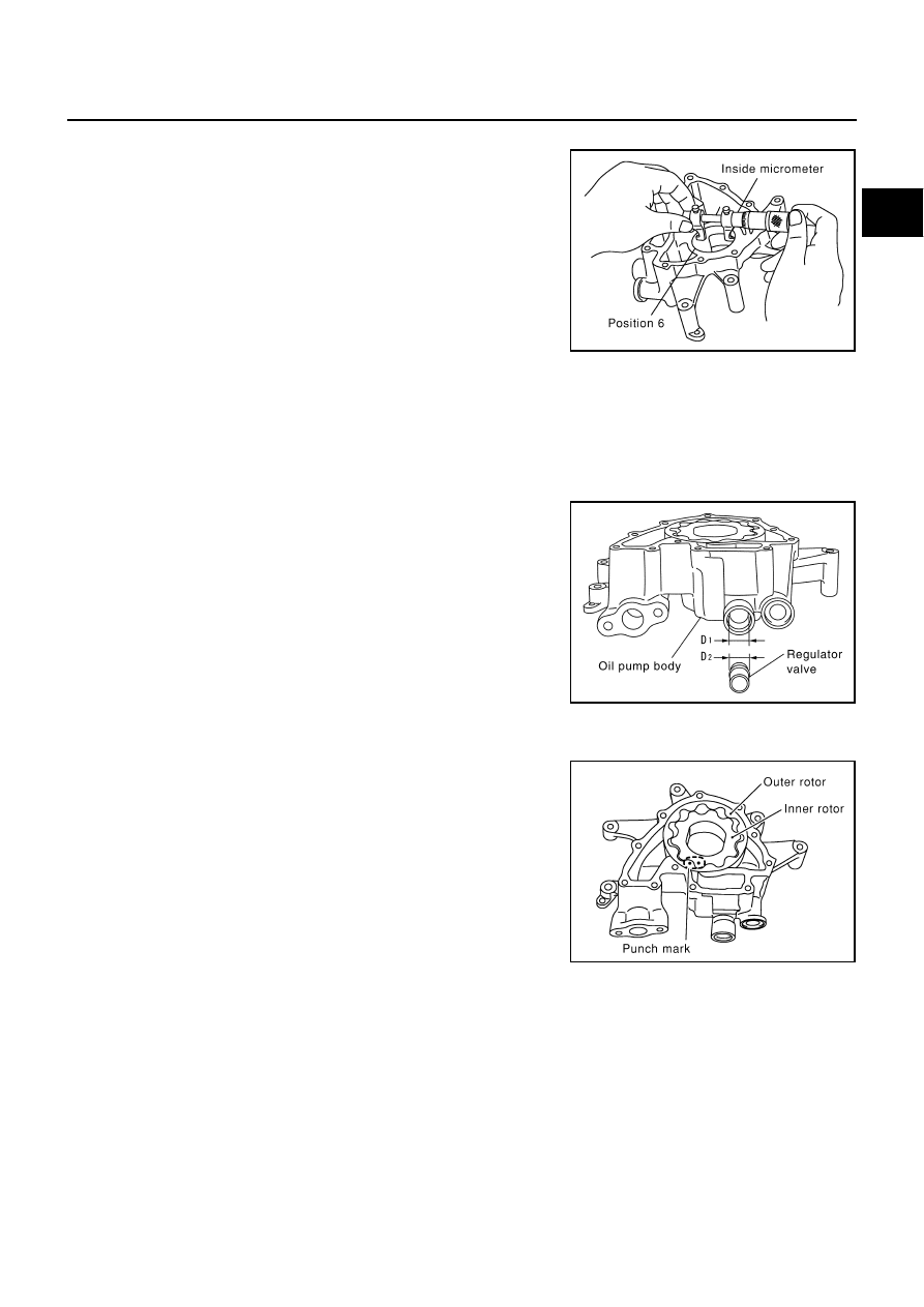
OIL PUMP BODY INNER DIAMETER
–
Measure the inner diameter of oil pump body with inside
micrometer. (Position 6)
OIL PUMP INNER DIAMETER TO OIL PUMP BODY CLEARANCE
–
(Clearance) = (Oil pump body inner diameter) – (Oil pump inner rotor outer diameter)
●
If the measured/calculated values are out of the standard, replace oil pump assembly.
Regulator Valve Clearance
(Clearance) = D
1
(Valve hole diameter) – D
2
(Regulator valve outer
diameter of valve)
●
If the calculated value is out of the standard, replace oil pump
assembly.
CAUTION:
●
Coat regulator valve with engine oil.
●
Make sure that it falls smoothly into regulator valve hole by
its own weight.
ASSEMBLY
Note the following, and assemble in the reverse order of disassembly.
●
Install oil pump inner rotor and oil pump outer rotor with the
punched marks on the oil pump cover side.
PBIC0142E
Standard
: 0.045 - 0.091 mm (0.0018 - 0.0036 in)
Standard
: 0.040 - 0.097 mm (0.0016 - 0.0038 in)
PBIC0143E
PBIC0144E
LU-34
[VK45DE]
SERVICE DATA AND SPECIFICATIONS (SDS)
SERVICE DATA AND SPECIFICATIONS (SDS)
PFP:00030
Standard and Limit
NBS004QI
ENGINE OIL PRESSURE
Unit: kPa (kg/cm
2
/psi)
*: Engine oil temperature at 80
°
C (176
°
F)
ENGINE OIL CAPACITY (APPROXIMATE)
Unit:
(US qt, Imp qt)
OIL PUMP
Unit: mm (in)
REGULATOR VALVE
Unit: mm (in)
Engine speed
Approximate discharge oil pressure*
Idle speed
More than 98 (1.0, 14)
2,000 rpm
More than 294 (3.0, 43)
Drain and refill
With oil filter change
5.5 (5-3/4, 4-7/8)
Without oil filter change
4.9 (5-1/8, 4-1/4)
Dry engine (engine overhaul)
6.7 (7-1/8, 5-7/8)
Oil pump body to oil pump outer rotor radial clearance
0.114 - 0.200 (0.0045 - 0.0079)
Oil pump inner rotor to oil pump outer rotor tip clearance
Below 0.180 (0.0071)
Oil pump body to oil pump inner rotor axial clearance
0.030 - 0.070 (0.0012 - 0.0028)
Oil pump body to oil pump outer rotor axial clearance
0.030 - 0.090 (0.0012 - 0.0035)
Oil pump inner rotor to oil pump body clearance
0.045 - 0.091 (0.0018 - 0.0036)
Regulator valve to oil pump body clearance
0.040 - 0.097 (0.0016 - 0.0038)
Нет комментариевНе стесняйтесь поделиться с нами вашим ценным мнением.
Текст