Infiniti M35/M45 Y50. Manual — part 110
ASSEMBLY
AT-363
D
E
F
G
H
I
J
K
L
M
A
B
AT
3.
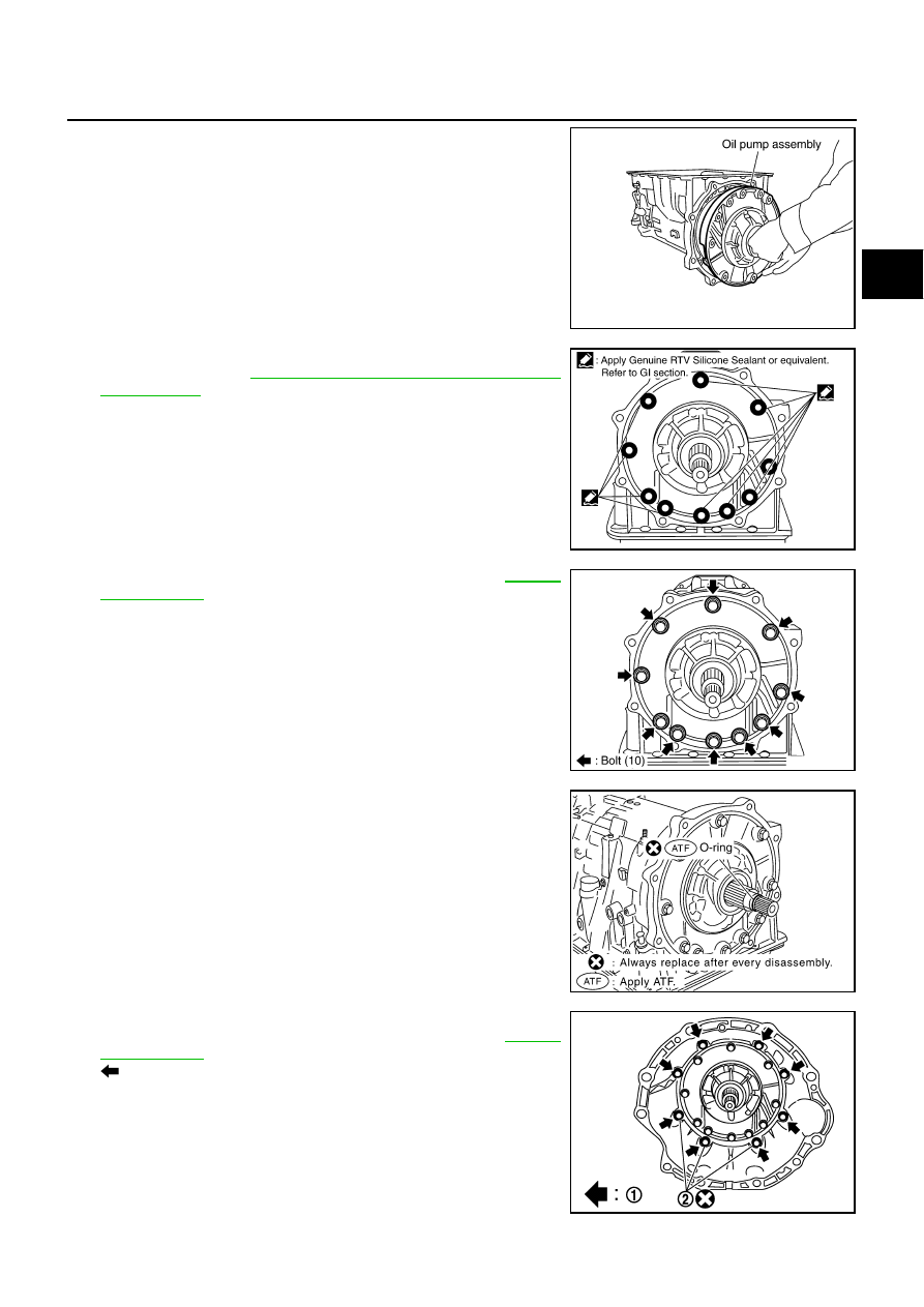
Install oil pump assembly in transmission case.
CAUTION:
Apply ATF to oil pump baring.
4.
Apply recommended sealant (Genuine RTV Silicone Sealant or
equivalent. Refer to
GI-47, "Recommended Chemical Products
.) to oil pump assembly as shown in the figure.
CAUTION:
Completely remove all moisture, oil and old sealant, etc.
from the oil pump mounting bolts and oil pump mounting
bolt mounting surfaces.
5.
Tighten oil pump bolts to the specified torque. Refer to
.
CAUTION:
Apply ATF to oil pump bushing.
6.
Install O-ring to input clutch assembly.
CAUTION:
●
Do not reuse O-ring.
●
Apply ATF to O-ring.
7.
Install converter housing to transmission case. Tighten con-
verter housing bolts (1) to the specified torque. Refer to
.
: Bolt (8)
CAUTION:
Do not reuse self-sealing bolt (2).
SCIA2811E
SCIA5321E
SCIA2300E
SCIA5011E
SCIA7985E

AT-364
ASSEMBLY
8.
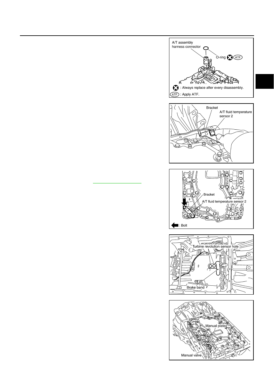
Make sure that brake band does not close turbine revolution
sensor hole.
9.
Install control valve with TCM.
a.
Connect TCM connector and park/neutral position switch con-
nector.
b.
Install A/T assembly harness connector to control valve with
TCM.
c.
Connect TCM connectors.
SCIA5034E
SCIA5449E
SCIA5450E
SCIA5447E
ASSEMBLY
AT-365
D
E
F
G
H
I
J
K
L
M
A
B
AT
d.
Install O-ring to A/T assembly harness connector.
CAUTION:
●
Do not reuse O-ring.
●
Apply ATF to O-ring.
e.
Install A/T fluid temperature sensor 2 to bracket.
f.
Install A/T fluid temperature sensor 2 (with bracket) in control
valve with TCM. Tighten A/T fluid temperature sensor 2 bolt to
the specified torque. Refer to
.
CAUTION:
Adjust bolt hole of bracket to bolt hole of control valve.
g.
Install control valve with TCM in transmission case.
CAUTION:
●
Make sure that turbine revolution sensor securely installs
turbine revolution sensor hole.
●
Hang down revolution sensor harness toward outside so
as not to disturb installation of control valve with TCM.
●
Adjust A/T assembly harness connector of control valve
with TCM to terminal hole of transmission case.
●
Assemble it so that manual valve cutout is engaged with
manual plate projection.
SCIA5155E
SCIA5264E
SCIA5301E
SCIA5034E
SCIA5035E
AT-366
ASSEMBLY
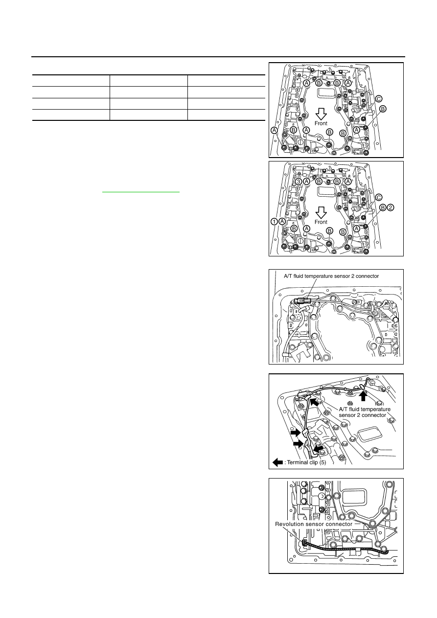
h.
Install bolts A, B and C to control valve with TCM.
i.
Tighten bolt 1, 2 and 3 temporarily to prevent dislocation. After
that tighten them in order (1
→
2
→
3), and then tighten other
bolts. Tighten control valve bolts to the TCM with specified
torque. Refer to
10. Connect A/T fluid temperature sensor 2 connector.
11. Securely fasten terminal cord assembly and A/T fluid tempera-
ture sensor 2 harness with terminal clips.
12. Connect revolution sensor connector.
Bolt symbol
Length mm (in)
Number of bolts
A
42 (1.65)
5
B
55 (2.17)
6
C
40 (1.57)
1
SCIA5025E
SCIA5037E
SCIA5023E
SCIA5446E
SCIA7524E
Нет комментариевНе стесняйтесь поделиться с нами вашим ценным мнением.
Текст