Skoda Superb (2019 year). Manual — part 7
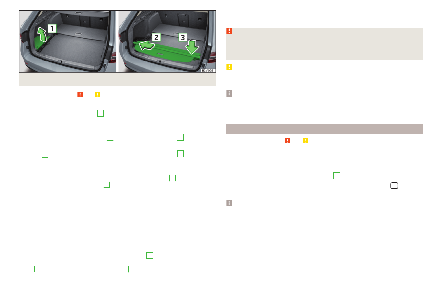
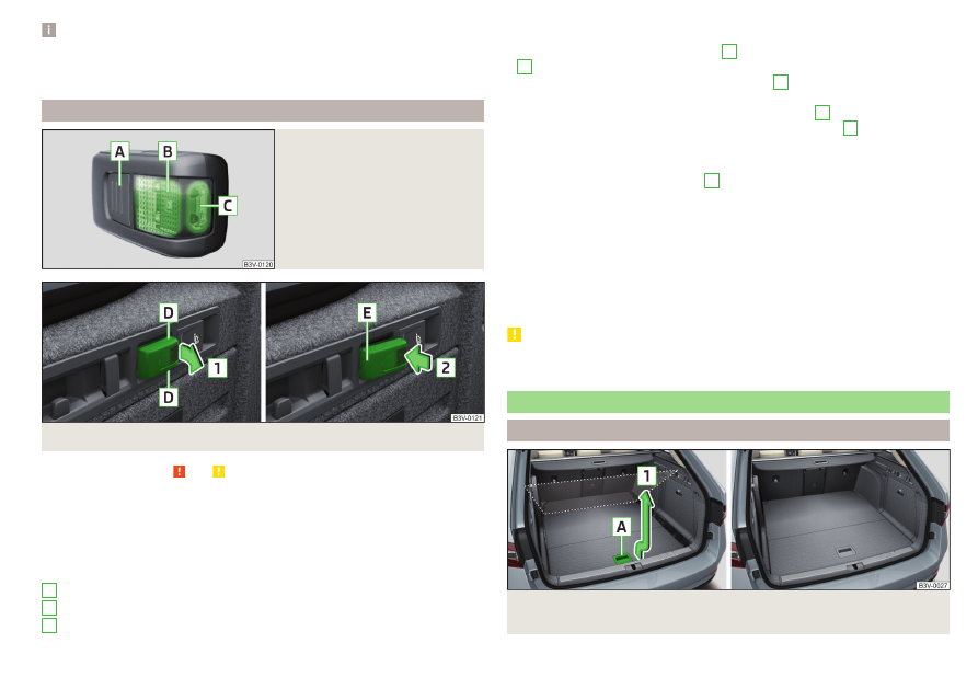
Fig. 149 Remove the left side cover / store roll-up cover
Read and observe and on page 105 first.
Extending
›
Grasp the cover at grip-point
A
and pull it out in the direction of the arrow
1
until it audibly clicks into place
.
Retracting
›
Push the cover in the handle area
A
in the direction of arrow
2
. The cover
rolls up automatically to the intermediate position
B
.
The cover rolls up fully by pressing the cover in the handle area
A
in direction
of arrow
3
. The rolled-up cover can now be removed.
Removing/inserting
›
Press on the side of the cross bar in the direction of arrow
4
and remove
the cover in the arrow direction
5
.
Insertion takes place in reverse order.
Stowage
If the vehicle is equipped with the variable loading floor, then the removable
roll-up luggage compartment cover can be stowed in the recesses of the lug-
gage compartment side trim.
›
Fold the variable loading floor into the upper position
.
›
Open the side trays on both sides of the luggage compartment and remove
›
Remove the left side cover in the arrow direction
1
.
›
Insert the roll-up cover in the recesses of the side trim in the direction of ar-
row
2
and stow in the direction of arrow
3
.
›
Reinsert the left side cover in the opposite direction to the arrow
1
.
›
Close the side compartments on both sides of the luggage compartment.
›
Fold out the variable loading floor to the upper position.
WARNING
No objects should be placed on the roll-up cover - there is a risk of damage
to the cover and a risk of injury in the event of a sudden stop or a vehicle
collision!
CAUTION
It is possible that the roll-up luggage compartment cover rolls more slowly
during winter weather conditions. This is not a defect.
Note
If you want to stow the roll-up luggage compartment cover and the multifunc-
tion pocket at the same time, then it is necessary that the rear part of the roll-
up luggage compartment covers the multifunction pocket.
Roll-up cover - automatic rolling-up
Read and observe and on page 105 first.
The automatic rolling up of the roll-up cover (hereafter as function) eases ac-
cess to the luggage compartment.
When opening the boot lid with the function activated, the roll-up cover auto-
matic rolls-up of the intermediate position
B
Deactivating/activating can be carried out in Infotainment in the
/ →
Opening and closing in progress.
Note
The setting (activation/deactivation) of the automatic rolling up is stored (de-
pending on the Infotainment type) in the active user account personalisation
109
Transport of cargo
-------------------------------------------------------------------------------------------------------------------------------------------------------------
Side storage compartment and trays
Fig. 150 Side shelf removal / open side pocket
Read and observe and on page 105 first.
Located at the two sides of the luggage compartment, depending on vehicle
equipment are side trays
- or lockable side compartments
- .
The space behind the tray and in the tray is provided for storing small objects
up to a total weight of 2.5 kg.
Side compartment
›
Remove the storage compartment cover in the direction of the ar-
row
- .
To insert, proceed in reverse order.
Side compartment
›
To open, pull the handle in direction of arrow
1
and open the compartment
in the direction of arrow
2
›
To close, swivel the compartment against the direction of arrow
2
.
Cargo element
Fig. 151 Taking out cargo elements: Version 1/version 2
Fig. 152 Taking out cargo elements: Variant 3/load fastening example
Read and observe and on page 105 first.
The cargo elements are designed for mounting and securing loads with a maxi-
mum gross weight of 8 kg.
›
Before use, remove the Cargo elements in the direction of the arrows
- .
›
Use the cargo elements to secure the load as close as possible to the rear
seats
.
›
After use, stow the Cargoelements in their original position.
110
Using the system
-------------------------------------------------------------------------------------------------------------------------------------------------------------
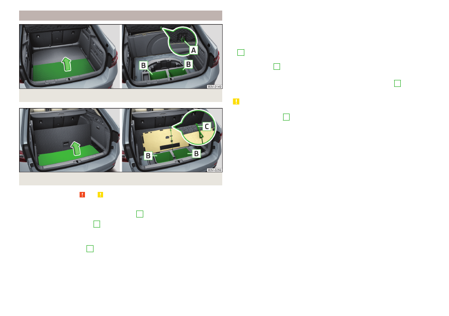
Storage compartments under the floor covering
Fig. 153 Variant 1: Lifting floor covering/storage compartments
Fig. 154 Variant 2: Lifting floor covering/storage compartments
Read and observe and on page 105 first.
For vehicles that are not equipped with an emergency spare wheel located un-
der the flooring of the luggage compartment
B
or
Every storage compartment
B
is designed for storing small objects of up to
15 kg. in weight in total.
Using the storage compartments - variant 1
›
Lift the flooring via loop
A
in the direction of arrow
ly fold back or fasten using the loop on the hook on the luggage compart-
ment cover.
›
Stow the cargo in the storage compartments.
›
Fold back the flooring against the direction of the arrow or remove it from
the hook.
When transporting tall objects in the compartments, the flooring must be fol-
ded forward.
Using the storage compartments - variant 2
›
Dividing the luggage compartment with variable loading floor
›
Lift the floor covering in the direction of arrow
C
on the upper edge of the variable loading floor.
›
Stow the cargo in the storage compartments.
›
Unhook hook
C
and fold back the flooring against the direction of the arrow
(fold back the variable loading floor to the initial position if necessary).
When transporting tall objects in the compartments, the hook
C
must be
hooked onto the upper edge of the variable loading floor.
CAUTION
■
Before closing the boot lid check that the flooring is not attached to the
hook with the loop
A
- there is a risk of damaging the hook.
■
Before closing the boot lid, check that the cargo transported in the storage
compartments does not strike against the luggage compartment cover - there
is a risk of damage to the lid.
111
Transport of cargo
-------------------------------------------------------------------------------------------------------------------------------------------------------------
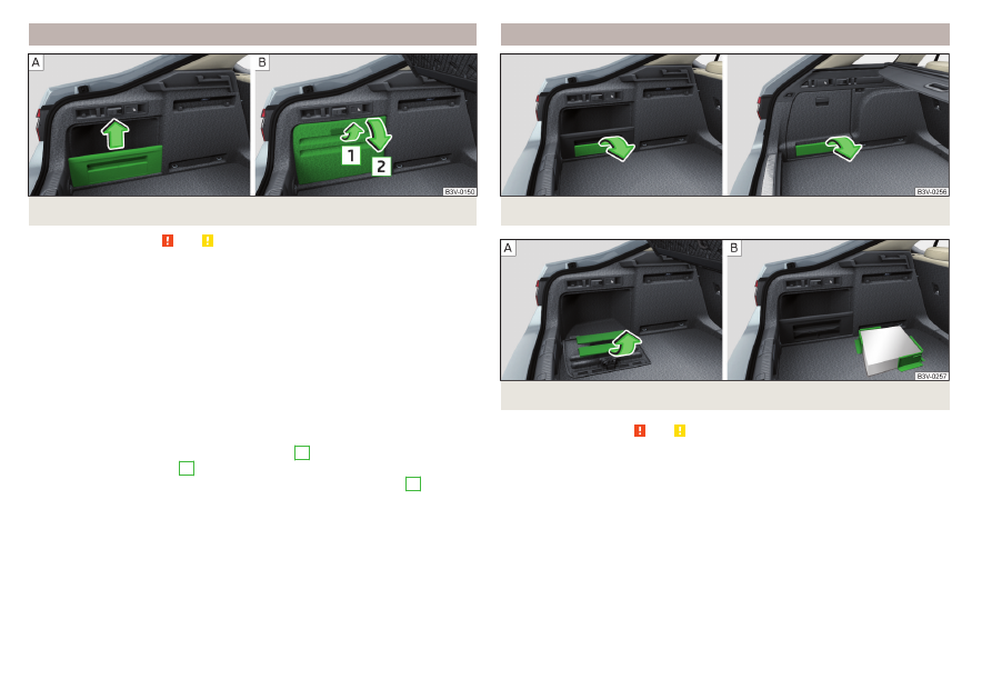
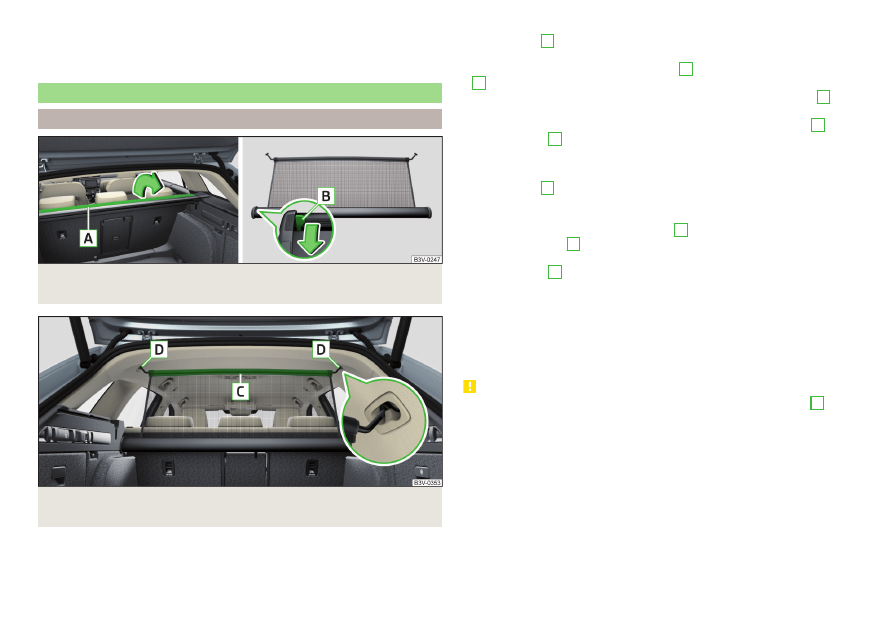
Multi-function pocket
Fig. 155 Multifunction pocket: Pull out/insert/push in/remove
Fig. 156 Remove the left side cover / store multifunction tray
Read and observe and on page 105 first.
The multifunction pocket (following as pocket) is provided for the storage of
clothing and light objects with no sharp edges.
The maximum permissible load of the multifunction box is 3 kg.
Removal and fitting
›
Fold down the front hooks on both sides of the luggage compartment in the
direction of arrow
1
›
Grasp the rear bar
A
with both hands and withdraw the pocket in arrow di-
rection
2
.
›
Place the rear bar onto the two hooks that are folded forward in the direc-
tion of the arrow
3
all the way to the stop.
Pushing in
›
Remove the rear bar from the hooks in the direction of arrow
4
and push in
the pocket in the direction of arrow
5
›
Place the rear bar against the front bar and press them together at both ends
B
.
›
The front hooks on both sides of the luggage compartment fold back oppo-
site to the direction of arrow
1
.
Removing/inserting
›
Remove the roll-up luggage compartment cover
.
›
Remove the pocket from the fittings in the direction of the arrow
6
Insertion takes place in reverse order.
›
Insert the end of the bar marked in the right-hand mounting, and the end
marked in the left-hand mounting. The arrows should be pointing forward.
Stowage
If the vehicle is equipped with the variable loading floor, then the removable
pocket cover can be stowed in the recesses of the luggage compartment side
trim.
›
Fold the variable loading floor into the upper position
›
Open the side trays on both sides of the luggage compartment
page 110 - .
›
Remove the left side cover in the arrow direction
1
›
Insert the pocket in the recesses of the side trim in the arrow direction
2
and stow in the direction of arrow
3
.
›
Reinsert the left side cover in the opposite direction to the arrow
1
.
›
Close the side compartments on both sides of the luggage compartment.
›
Fold out the variable loading floor to the upper position.
112
Using the system
-------------------------------------------------------------------------------------------------------------------------------------------------------------
Note
If you want to stow the roll-up luggage compartment cover and the multifunc-
tion pocket at the same time, then it is necessary that the rear part of the roll-
up luggage compartment covers the multifunction pocket.
Removable light
Fig. 157
Removable light
Fig. 158 Removing light/inserting light
Read and observe and on page 105 first.
The lamp is for the illumination of the luggage compartment or it can be used
as a portable lamp.
The lamp is equipped with a magnet. As a result, this can, for example, be fitted
to the vehicle body.
Description of the light
Button to turn the light that has been removed on / off
Part that lights up when the lamp is in the mount
Part that lights up when the lamp is not in the mount
A
B
C
If the light is in the mount, this will illuminate when the boot lid is opened.
›
To remove, hold the light in the area
D
and swivel in the direction of arrow
1
.
›
To switch on the removed light, press button
A
» Fig. 157
. Pressing the light
again will switch it off.
›
To insert, first of all insert the light with the rear part
E
into the mount
and then push the light in the direction of arrow
2
until it audibly
clicks into place.
If the light is not switched off and is correctly inserted in the mount, the LED
diodes in the front part of the light
C
are automatically switched off.
If the lamp is not correctly inserted into the holder, this does not light up when
the boot lid is opened and the rechargeable batteries are not charged.
Lamp charges
The lamp is supplied by three rechargeable type NiMH AAA batteries (voltage
1.2 V). The batteries are charged continuously with the engine running (to fully
charge the battery takes approximately 3 hours).
Replace batteries
CAUTION
The light is not waterproof, so it must be protected from humidity - otherwise
there is risk of damage.
Variable loading floor in the luggage compartment (Estate)
Positions of the variable loading floor
Fig. 159 Set variable loading floor to the upper position / variable load-
ing floor in the upper position
113
Transport of cargo
-------------------------------------------------------------------------------------------------------------------------------------------------------------
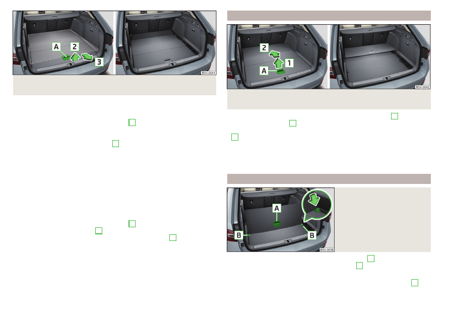
Fig. 160 Set variable loading floor to the lower position / variable load-
ing floor in the lower position
The variable loading floor can be set to the upper or lower position.
Set to the upper position
›
Lift the variable loading floor by the handle
A
pull towards you.
›
Lift the variable loading floor to the height of the roll-up luggage compart-
ment cover in the direction of arrow
1
until you hear the clicking sound and
press forward.
The space below the variable loading floor can be used for stowing objects
such as the removed roll-up luggage compartment cover
ti-function pocket
etc.
The maximum permissible load of the variable loading floor is 75 kg. For the
transport of heavy loads, adjust the variable loading floor in the lower position
.
Set into the lower position
›
Check that the area below the variable loading floor is empty.
›
Lift the variable loading floor by the handle
A
edge in the direction of arrow
2
.
›
Pull the loading floor towards you in the direction of arrow
3
until it sinks to
the bottom position, and push forward.
Fold together / fold out the variable loading floor
Fig. 161 Fold up variable loading floor / folded variable cargo floor in the
upper position
›
To fold together, hold the variable loading floor by the handle
A
and lift in
the direction of arrow
1
›
Fold up the variable loading floor by moving it in the direction of the arrow
2
.
Folding out takes place in reverse order.
The variable loading floor is folded together / out in the same way in the upper
and lower position.
Dividing the luggage compartment
Fig. 162
Dividing the boot with variable
loading floor
›
To divide, lift the variable loading floor by the handle
A
and push in the rear
edge of the variable loading floor in the grooves
B
in the direction of the ar-
row
.
The variable loading floor is secured against movements in the grooves
B
.
114
Using the system
-------------------------------------------------------------------------------------------------------------------------------------------------------------
Folding out takes place in reverse order.
The variable loading floor is divided in the same way in the upper and lower po-
sition.
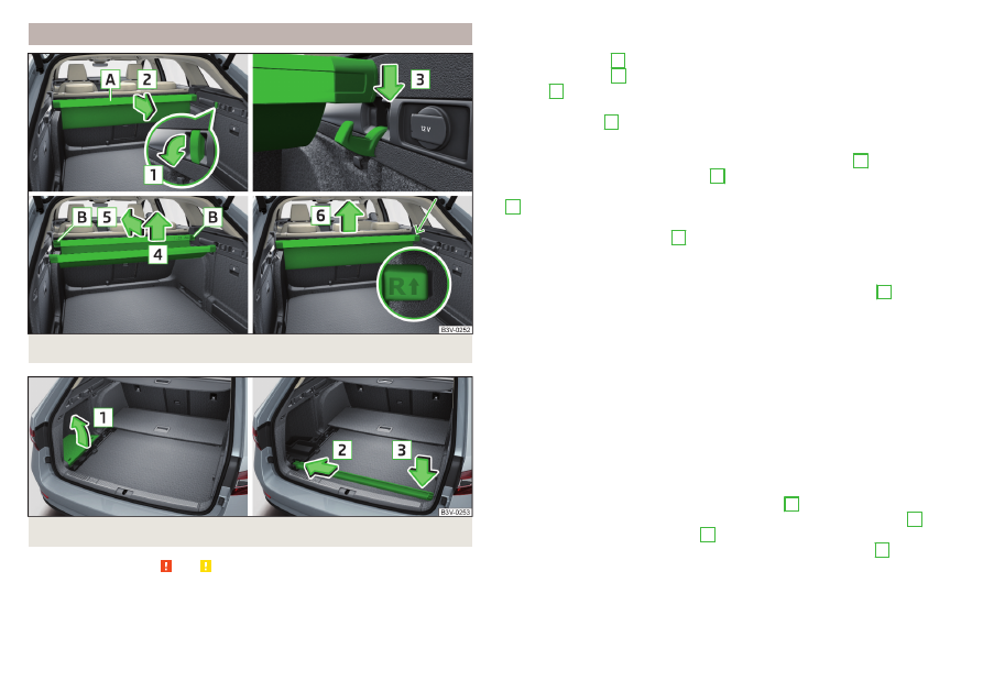
Net partition
Using the net partition
Fig. 163 Open part of the roll-up luggage compartment cover / release
lever
Fig. 164 Correctly secure net partition behind the front seats in the
pulled-out state
The net partition can either be pulled out and secured from behind the rear
seats or behind the front seats.
Pull out and secure the net partition behind the rear seats
›
Fold out part
A
of the roll-up luggage compartment cover in the direction of
arrow
›
Pull out the net partition at the crossbar
C
, insert in one of the mountings
D
and push forwards
›
Insert the crossbar on the other side of the vehicle in the mounting
D
in the
same way.
›
Make sure that the crossbar is firmly seated in the two mountings
D
.
›
Fold back part
A
of the roll-up luggage compartment cover in the opposite
direction of the arrow
Using the net partition behind the rear seats
›
Fold out part
A
of the roll-up luggage compartment cover in the direction of
arrow
›
First pull the crossbar back slightly on the one side and then on the other
side and remove it from the mountings
D
›
Hold the crossbar
C
in such a way that the net partition can slowly roll up
without being damaged.
›
Fold back part
A
of the roll-up luggage compartment cover in the opposite
direction of the arrow
Pull out and secure the net partition behind the front seats
The process is analogous to that for behind the rear seats. Before removing
the net partition, the rear seat backrests should be folded forwards. After roll-
ing up the net partition in the housing, the rear seat backrests should then be
folded back
CAUTION
If the net partition blocks when pulling it out, push the release lever
B
in the
direction of the arrow
.
115
Transport of cargo
-------------------------------------------------------------------------------------------------------------------------------------------------------------
Removing and installing the net partition housing
Fig. 165
Removing the net partition
housing
›
To remove, fold forwarded the rear seat backrests and open the rear right
door.
›
Push the housing
A
in the direction of the arrow
1
and remove it from the
mountings in the direction of the arrow
2
.
›
To install, insert the recesses on the housing
A
into the mountings on the
rear seat backrests and push the housing against the arrow
1
up to the
stop.
›
Fold the rear seat backrests to their original position.
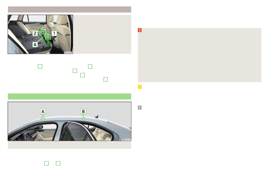
Transportation on the roof rack
Fig. 166 Attachment points
Depending on the equipment, the roof bars can be attached at the attachment
points
or to the roof rail.
The attachment points
A
and
B
are located on both sides of the vehicle
Mounting and dismounting of the roof bars is carried out according to the in-
structions provided.
Roof load
The maximum permitted weight of the load incl. the carrier is 100 kg.
WARNING
For road safety when transporting cargo on the roof rack, observe the fol-
lowing instructions.
■
Always distribute the load on the roof rack evenly and secure properly us-
ing suitable lashing straps or tensioning straps.
■
When transporting heavy objects or objects which take up a large area on
the roof rack system, the handling of the car may change as a result of the
displacement of the centre of gravity. The style of driving and speed must
therefore be adapted to the current circumstances.
■
The permissible roof load, permissible axle loads and permissible total ve-
hicle weight must not be exceeded under any circumstances – risk of acci-
dent!
CAUTION
■
Make sure that the sliding / tilting roof or the boot lid does not collide with
the roof load when opened.
■
Ensure the roof aerial is not impaired by the load being transported.
Note
We recommend that you use a roof rack from ŠKODA Original Accessories.
116
Using the system
-------------------------------------------------------------------------------------------------------------------------------------------------------------
Heating and ventilation
Heating, manual air conditioning system, Climatronic
Introduction
The heating heats and ventilates the vehicle interior. The air conditioning sys-
tem also cools and dehumidifies the vehicle interior.
The heating effect is dependent upon the coolant temperature, thus full heat
output only occurs when the engine has reached its operating temperature.
The cooling system works under the following conditions.
The cooling system is switched on.
The engine is running.
The outside temperature is below 2 ° C.
The blower is switched on.
Fogging is prevented when the cooling system is switched on.
It is possible to boost the effectiveness of the cooling system by briefly acti-
vating the air recirculation system
.
Health protection
To reduce health risks (e.g. common colds), the following instructions for the
use of the cooling system are to be observed.
▶
The difference between the indoor temperature and the outdoor air temper-
ature should not be greater than about 5 ° C.
▶
The cooling system should be turned off about 10 minutes before the end of
the journey.
▶
Once a year, the air conditioning should be disinfected by a specialist garage.
WARNING
■
The blower should always be on to prevent the windows from misting.
Otherwise there could be an accident.
■
Under certain circumstances, air at a temperature of about 5 °C can flow
out of the vents when the cooling system is switched on.
Note
■
The air inlet in front of the windscreen must be free of e.g. ice, snow or
leaves to ensure that the heating and cooling system operates properly.
■
After switching on the cooling Condensation from the evaporator of the air
conditioning may drip down and form a puddle below the vehicle. This is not a
leak!
■
If the coolant temperature is too high, the cooling system is switched off to
ensure that the engine cools down.
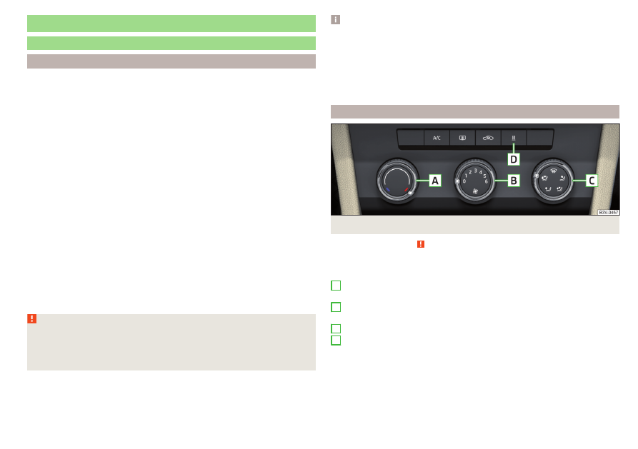
Heating and manual air conditioning
Fig. 167 Controls of the heating / air conditioning
Read and observe on page 117 first.
Individual functions can be set or switched on by turning the dial or pressing
the corresponding button
.
Setting temperature
▶
Reduce the temperature/
Increase the temperature
Set the blower speed (Level 0: Adjust the fan speed (level 0: fan off; level
6: highest speed)
Set the direction of the air outlet
Depending on equipment fitted:
▶
Auxiliary heating and ventilation on / switch off
▶
Switching the windscreen heater on/off
Switch the cooling system on/off
Switch on/off the rear window heating
Switch recirculation on/off
A
B
C
D
117
Heating and ventilation
-------------------------------------------------------------------------------------------------------------------------------------------------------------
When the function is switched on, the indicator lamp below the button lights
up.
Information on the cooling system
After pressing the button , the warning light underneath the button illumi-
nates even if not all conditions are met for the cooling system. The cooling
system starts to work as soon as the following conditions have been met
When the air distribution control is turned to position the cooling system is
activated.
Note
To ensure adequate thermal comfort, during operation of the manual air condi-
tioning there could be an increase in the engine idle speed in some circumstan-
ces.
Climatronic (automatic air conditioning)
Fig. 168 Front operating elements
Fig. 169
Rear operating elements
Read and observe on page 117 first.
Individual functions can be set or switched on by turning the dial or pressing
the corresponding button
.
Display the temperature setting for the left side
Display the temperature setting for the right side
Set the direction of the air outlet
Adjust fan speed (the setting is indicated by the number of illuminated
control lamps shown in the knob)
▶
Turn to the left: Reduce speed up to turning off the Climatronic
▶
Turn to the right: Increase speed
Adjust the temperature for the left side (or for both sides)
▶
Reduce the temperature/
Increase the temperature
Adjust the temperature for the right side (or for both sides)
▶
Reduce the temperature/
Increase the temperature
Depending on equipment fitted:
▶
Auxiliary heating and ventilation on / switch off
▶
Residual heat function on / off
Interior temperature sensor
Display of the temperature set in the rear
Set the rear temperature- deactivation/activation of the keys can be car-
ried out by pressing the button on the Climatronic → by tapping the
function surfaces on the Infotainment screen.
▶
Reduce the temperature/
Increase the temperature
Switch recirculation on/off
A
B
C
D
E
F
G
H
I
J
1)
Applies to left-hand drive vehicles.
2)
Applies to right-hand drive vehicles.
118
Using the system
-------------------------------------------------------------------------------------------------------------------------------------------------------------
Intense air flow to the windscreen on / off (when switching on, the air
flow to the windows and is also switched on)
Switch on/off the rear window heating
Switching the windscreen heater on/off
Setting Climatronic in Infotainment ( can also be operated with some
functions)
Synchronize the temperature inside the entire vehicle according to the
temperature setting on the driver's side
Switching automatic mode on
Switch the cooling system on/off
When the function is switched on, an indicator lamp lights up inside or below
the button.
Setting temperature
The temperature can be set on the Climatronic control unit or in Infotain-
ment
. In the range between 16 ° C to 29.5 ° C, an automatic tem-
perature control takes place.
At a temperature setting below 16 ° C, lights up in the temperature display,
the Climatronic functions with maximum cooling performance.
At a temperature setting over 29.5 ° C, lights up in the temperature display,
the Climatronic functions with maximum heating output.
Residual heat function
After switching off the ignition, the engine residual heat is used for heat reten-
tion in the vehicle interior. The function can only be switched on with the igni-
tion off within 30 minutes after stopping the engine. The residual heat func-
tion turns off after about 30 minutes, or when the battery has a low charge
state.
CAUTION
Do not cover the interior temperature sensor
H
the Climatronic could be affected.
Note
■
In order to ensure adequate thermal comfort, there may be an increase in en-
gine idle speed during operation of the Climatronic in some circumstances.
■
The setting of the Climatronic is stored in the active user account personali-
sation
Operate Climatronic in Infotainment
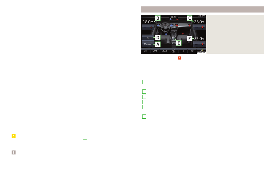
Fig. 170
Infotainment: example display of
the main Climatronic menu
Read and observe on page 117 first.
›
To display the main menu press the button on the Climatronic control
unit.
Function surfaces and screen display
A
Displays the current operation mode (or set the operation mode) of
the Climatronic
B
Set the desired temperature (front - left side)
C
Set the desired temperature (front - right side)
D
Setting the power in operation
E
Switching on/off and adjusting the fan speed, cooling system, air dis-
tribution and air recirculation
F
Set the desired temperature (rear)
Colour representation of the air flow from the air vents at the front
(Blue colour - temperature reduction / red colour - temperature in-
crease)
Switching on/off the Climatronic
Switch the temperature synchronisation on/off throughout the entire
interior of the vehicle according to the temperature setting on the
driver's side
Locking/unlocking of the temperature setting and heating of the rear
seats using the rear buttons
Switch Air Care function on/off
Set the auxiliary heater and ventilation
Switch the windscreen heating on/off
119
Heating and ventilation
-------------------------------------------------------------------------------------------------------------------------------------------------------------
Turn the steering wheel heating on/off
Other Climatronic settings
a)
When function is switched on, the symbol in the function surface is green.
Other Climatronic settings
Press the button on the Climatronic control panel → Tap the function sur-
face on the Infotainment screen.
■
Air con. profile - Setting the operating performance during operation (ap-
plies to Infotainment Swing)
■
Automatic air recirculation - Automatic re-circulated air mode on/off
■
Automatic auxiliary heater - Quick interior heating on/off
■
Automatic windscreen heating - Activates/deactivates the automatic windscreen
heating
Climatronic - automatic operation
Read and observe on page 117 first.
The automatic mode is used in order to maintain a constant temperature and
to demist the windows in the interior of the car.
›
To turn on, press
›
To turn off, press any button for the air distribution or change the blower
speed. The temperature regulation is continued.
Operating modes
Automatic mode works in three modes - moderate, medium, and intensive.
Setting the different modes is carried out via the function surface
D
on page 119.
After the automatic mode is switched on, Climatronic works in the last selec-
ted mode. The currently selected mode is displayed in the Infotainment dis-
play.
Air distribution control
Read and observe on page 117 first.
The recirculation mode prevents contaminated outside air getting into the In-
terior of the vehicle. In recirculated air mode air is sucked out of the interior of
the vehicle and then fed back into the interior.
›
To switch on, press the button. The warning light below the button lights
up.
›
To switch off, press the button again. The warning light below the button
goes out.
Heating and manual air conditioning system
If the air distribution control is set to position when the recirculation modes
is switched on, the recirculated-air mode is switched off. By pressing the
button, the air recirculation also in this position can be switched on again.
When the cooling system ( button) is switched on and the temperature reg-
ulator is “turned” to the left, the recirculated-air mode is switched on.
Climatronic
The Climatronic can have a sensor that measures the air recirculation mode
and automatically turns on if there is an increased concentration of pollutants
in the incoming air.
When the pollutant concentration decreases to the normal level, the recircula-
ted air mode is automatically switched off.
Automatic switch-on/switch-off of the air recirculation function can be set in
the Infotainment screen, by pressing the button on the Climatronic and by
then pressing the function surface → Automatic air recirculation.
A shut-off of the air recirculation function takes place automatically by press-
ing the button, possibly depending on the moisture conditions in the vehi-
cle interior.
WARNING
The air recirculation cannot be switched on for a longer period of time be-
cause there is no supply of fresh air from the outside. “Stale air” may result
in fatigue in the driver and occupants, reduce attention levels and also
cause the windows to mist up. As soon as the windows mist up, turn the air
recirculation mode off immediately - there is a risk of accident!
CAUTION
We recommend not smoking in the vehicle when the recirculating air opera-
tion is switched on. The smoke sucked from inside the vehicle is deposited on
the evaporator of the air conditioner. This produces a permanent odour when
the air conditioning system is operating which can only be eliminated through
considerable effort and expense (replacement of compressor).
120
Using the system
-------------------------------------------------------------------------------------------------------------------------------------------------------------
Climatronic - Air Care function
Fig. 171
Example display of the Air Care
function
Read and observe on page 117 first.
The Air CareFunction reduces pollutant penetration contained in the outside
air into the vehicle.
When the function is activated, the air in the vehicle is circulated and cleaned
at the same time. The cleaning process is displayed by the zones displayed in
the Infotainment screen.
›
To switch on/off, press the button on the Climatronic control panel, and
then tap on the function surface → Active on the Infotainment
screen
.
To ensure correct Air Care functioning, all doors and windows including the
panoramic sliding/tilting roof must be closed.
When opening a door or a window, the corresponding message is displayed in
the Infotainment screen.
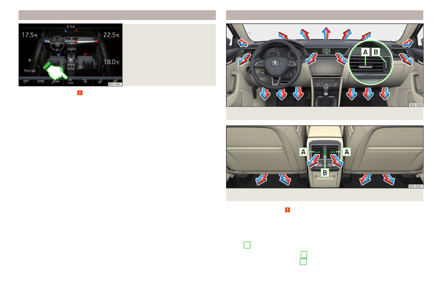
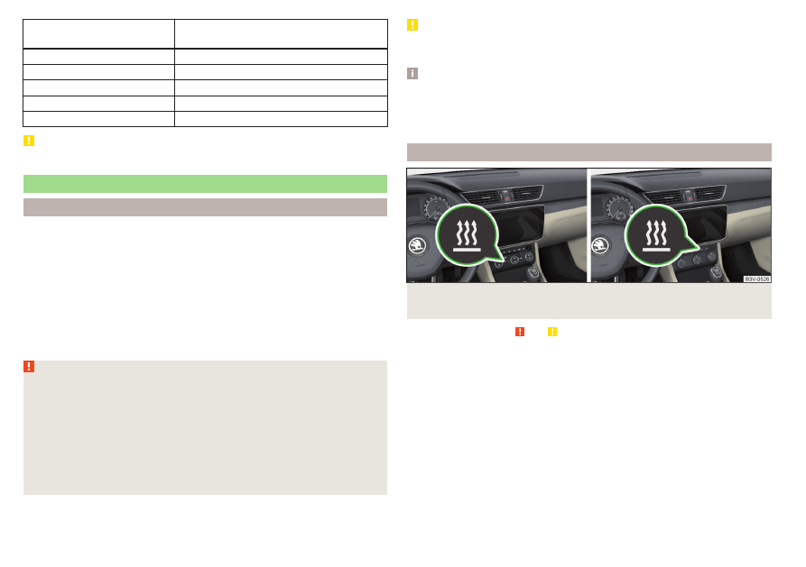
Air outlet vents
Fig. 172 Air vents at the front
Fig. 173 Air vents at the rear
Read and observe on page 117 first.
The direction of airflow can be adjusted using the air outlet vents 3, 4
and 6
, and the vents can be opened and closed individually.
The setting of the airflow direction is carried out by moving the adjustment el-
ement
A
in the desired direction.
›
To open, turn the controller
B
or
upwards.
›
Toclose, turn the controller
B
Depending on the setting of the air distribution, the air stream comes out of
the following air vents.
121
Heating and ventilation
-------------------------------------------------------------------------------------------------------------------------------------------------------------
Set the direction of the air
outlet
Air vents
1, 2, 4
1, 2, 4, 5, 7
3, 4, 6
4, 5, 7
3, 4, 5, 6, 7
CAUTION
Do not cover the air vents - the air distribution could be compromised.
Auxiliary heating (auxiliary heating and ventilation)
Introduction
The auxiliary heating heats the vehicle interior as well as the engine. For heat-
ing, fuel is consumed from the fuel tank.
The auxiliary ventilation enables fresh air to flow into the vehicle interior with
the engine switched off, whereby the interior temperature is effectively de-
creased (e.g. with the vehicle parked in the sun).
The auxiliary heating (auxiliary heating and ventilation) (referred to just as auxil-
iary heating in the following) ensures the heating / ventilation depending on
the setting of the air conditioning and the air outlet vents before switching off
the ignition.
WARNING
■
The auxiliary heating must never be operated in closed rooms (e.g. garag-
es) – risk of poisoning!
■
The auxiliary heating must not be allowed to run during refuelling – risk of
fire.
■
The exhaust pipe of the auxiliary heating is located on the underside of
the vehicle. If you want to use the auxiliary heating, do not park the car in
places where the exhaust fumes can come into contact with flammable
materials such as dry grass, undergrowth, leaves, spilled fuel etc. - risk of
fire.
CAUTION
The air inlet in front of the windscreen must be free (e.g. of ice, snow or
leaves) to ensure that the auxiliary heating operates properly.
Note
■
The auxiliary heating switches the blower on, if it has achieved a coolant tem-
perature of approx. 50 °C.
■
In the engine compartment, water vapour may form during the operation of
the heater.
Power on/off
Fig. 174 Button for switching on / off (Climatronic / manual air condi-
tioning)
Read and observe and on page 122 first.
Functional requirements of the auxiliary heating.
The charge state of the vehicle battery is sufficient.
The fuel supply is adequate (the warning light
is not illuminated in the
instrument cluster).
Manual on / off
▶
Using the button on the control panel of the air conditioner
.
▶
Using the (switch on) / (switch off) button on the remote control opera-
tion.
Automatic on / off
▶
Via an enabled pre-selection time in Infotainment.
▶
According to the environmental conditions.
122
Using the system
-------------------------------------------------------------------------------------------------------------------------------------------------------------
After switching off the system, the coolant pump and the auxiliary heating will
continue running a little while longer in order to burn the remaining fuel in the
heating.
Setting automatic on / off
Climatronic: On the Climatronic, press the button → tap the function
surface on the Infotainment screen. There will be a display of the last set oper-
ating mode with the option to change this.
Individually controlled air conditioning: In the Infotainment system, in menu
/ tap the function surface.
Then follow the instructions in the Infotainment screen.
When automatic switching on is activated, the warning light in the symbol
button lights up for about 10 seconds after the ignition is turned off
.
Operation in Infotainment
Fig. 175 Auxiliary heater: Main menu/set preset time
Read and observe and on page 122 first.
Call up the main menu
›
On the Climatronic, press the button → Tap on the function surface in
the Infotainment screen.
Or vehicles with manual air conditioning:
›
In the Infotainment system, in menu
/ tap the function surface.
Function surfaces and screen display
» Fig. 175
Departure time - Day and time when the vehicle is to be ready for use
Setting the operating mode (heating / ventilation)
A
B
List of pre-selected times, activation / deactivation of the preset time
Set the preset times 1-3 and the duration (10-60 minutes)
When heating the windows are shown in red / with continuous aeration,
the windows are shown in blue
Currently displayed preset time
Activation of the currently displayed preset time
Setting the departure time: Day, hour, minute
Only one preset time can be active. The activated preset time will be deactiva-
ted again after it has started automatically. For the next start, activate one of
the preset times.
Note
■
When selecting the day in the preset time, there is an option between Sun-
day and Monday without the specified day. If this setting is selected, the vehi-
cle will be ready for use at the selected time, regardless of the current day.
■
If a different time is set, the activated preset time is automatically deactiva-
ted. The preset time must be reactivated.
Radio remote control
Fig. 176
Radio remote control
Read and observe and on page 122 first.
Description of the remote control
Warning light
Aerial
Switch on the auxiliary heating
Switch off the auxiliary heating
C
D
E
F
G
H
A
B
123
Heating and ventilation
-------------------------------------------------------------------------------------------------------------------------------------------------------------
The auxiliary heating is switched on/off by pressing the button. To switch the
remote control on or off, hold the remote control vertically, with the aerial
B
pointing upwards. Do not cover the antenna with the fingers or the
palm of the hand.
Display warning light
A
Meaning
Lights up green for 2 seconds.
The auxiliary heating has been switch-
ed on.
Lights up red for 2 seconds.
The auxiliary heating has been switch-
ed off.
Slowly flashes green for 2 seconds.
The ignition signal was not received.
Quickly flashes green for 2 seconds.
The auxiliary heating is blocked, e.g.
because the tank is nearly empty or
there is a fault in the auxiliary heating.
Flashes red for 2 seconds.
The switch off signal was not re-
ceived.
Lights up orange for 2 seconds, then
green or red.
The battery is weak, however the
switching on or off signal was re-
ceived.
Lights up orange for 2 seconds, then
flashes green or red.
The battery is weak, however the
switching on or off signal was not re-
ceived.
Flashes orange for 5 seconds.
The battery is discharged, however
the switching on or off signal was not
received.
Replace the battery
.
CAUTION
■
The remote control must be protected against moisture, severe shocks and
direct sunlight - otherwise, there is a risk of damage to the remote control.
■
The range of the remote control with a charged battery is a few hundred me-
tres (depending on obstructions between the remote control and the vehicle,
weather conditions, the battery condition etc.).
124
Using the system
-------------------------------------------------------------------------------------------------------------------------------------------------------------
Нет комментариевНе стесняйтесь поделиться с нами вашим ценным мнением.
Текст