Mitsubishi Lancer Evolution IX. Manual — part 620
TRANSMISSION ASSEMBLY
MANUAL TRANSMISSION (FF)
22A-163
TRANSMISSION ASSEMBLY
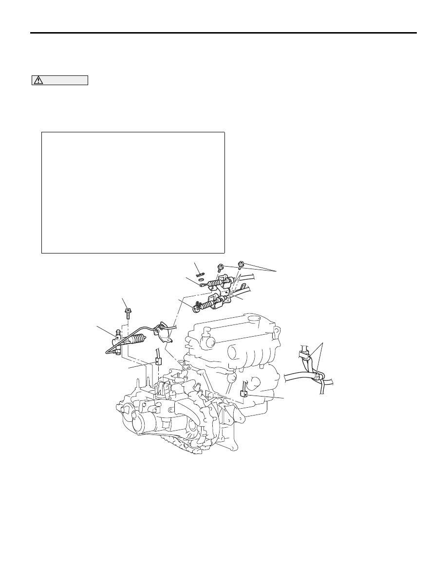
REMOVAL AND INSTALLATION
M1221002700590
CAUTION
• If the Brembo brake caliper is used, be careful not to hit parts and tools against the caliper when
servicing because the paint of the caliper may delaminate.
• *: Indicates parts which should be initially tightened, and then fully tightened after placing the
vehicle horizontally and loading the full weight of the engine on the vehicle body.
Pre-removal and Post-installation Operation
• Transfer Assembly Removal and Installation (Refer to
).
• Battery and Battery Tray Removal and Installation.
• Strut Tower Bar Removal and Installation (Refer to
GROUP 42
− Strut Tower Bar
).
• Strut assembly mounting bolt temporary Installation
<Pre-removal only>
• Air duct, Air Cleaner Assembly and Air Intake Hose
Removal and Installation (Refer to GROUP 15
− Air
Cleaner ).
• Air By-pass Hose, Air Hose E, Air Pipe C and Air Hose D
Removal and Installation (Refer to GROUP 15
• Starter Assembly Removal and Installation (Refer to
GROUP 16
AC211629AC
1
2
3
4
5
6
7
8
18 ± 3 N·m
18 ± 3 N·m
Removal steps
1.
Main harness clamp connection
2.
Back-up lamp switch connector
connection
3.
Vehicle speed sensor connector
connection
4.
Snap pin
5.
Shift cable connection
<<
A
>>
6.
Select cable connection
7.
Control cable assembly and
bracket
8.
Clutch release cylinder and clutch
oil pipe
Removal steps (Continued)

TRANSMISSION ASSEMBLY
MANUAL TRANSMISSION (FF)
22A-164
REMOVAL SERVICE POINTS
<<A>> SELECT CABLE CONNECTION
REMOVAL
Set the clip of the select cable as shown in figure 1
and 2, and disconnect the select cable.
<<B>> TRANSMISSION MOUNTING
INSULATOR ASSEMBLY REMOVAL
Jack up and support the engine and transmission
assembly, and remove the transmission mounting
insulator assembly.
AC211628AC
11
12
12
13
16
14
15
15
9
10
9
9
10
82 ± 7 N·m*
47 ± 7 N·m*
26 ± 5 N·m
9.0 ± 1.0 N·m
48 ± 5 N·m
48 ± 5 N·m
48 ± 5 N·m
48 ± 5 N·m
8.8 ± 1.0 N·m
48 ± 5 N·m
Removal steps
9.
Transmission assembly upper part
coupling bolt
10. Harness clump
<<
B
>>
11. Transmission mounting insulator
assembly
>>
A
<< 12. Transmission mounting insulator
stopper
13. Transmission mounting insulator
<<
C
>>
•
Engine assembly supporting
•
Raise the vehicle.
14. Bell housing cover
<<
D
>>
•
Clutch release bearing separation
15. Transmission assembly lower part
coupling bolt
16. Transmission assembly
Removal steps (Continued)
AC211243
AC
1
2
Select cable
AC211722
AC
Engine and transmission assembly
Garage jack

TRANSMISSION ASSEMBLY
MANUAL TRANSMISSION (FF)
22A-165
<<C>> ENGINE ASSEMBLY SUPPORTING
1. <Engine hanger (special tool MB991895) is used>
(1) Set special tool MB991895 to the strut
mounting nuts and the radiator support upper
insulator mounting bolts, which are located in
the engine compartment, as shown.
(2) Set special tool MB991454 to hold the engine
and transmission assembly.
2. <Engine hanger (special tool MB991928) is used>
(1) Assemble the engine hanger (special tool
MB991928). Set the following parts to the
base hanger.
• Slide bracket (HI)
• Foot (standard) (MB991932)
• Joint (90) (MB991930)
(2) Set the engine hanger (special tool
MB991928) to the strut mounting nuts and the
radiator support upper insulator mounting
bolts, which are located in the engine
compartment, as shown.
NOTE: Adjust the engine hanger balance by
sliding the slide bracket (HI).
(3) Set special tool MB991454 to hold the engine
and transmission assembly.
<<D>> CLUTCH RELEASE BEARING
SEPARATION
1. Remove the service hole cover of the clutch
housing.
CAUTION
• Do not insert the flat-tipped driver before
pressing the release fork towards direction A.
• Do not insert the flat-tipped driver between
the wedge collar and the wave spring.
2. Insert the flat-tipped driver between the release
bearing and wedge collar while slightly pressing
the release fork towards direction A by hand.
CAUTION
If the driver cannot be turned slightly (the release
bearing cannot be disconnected), remove the
flat-tipped driver and press the release fork sev-
eral times towards direction A, then retry again. If
the release bearing is pried off forcibly, it may be
damaged.
3. Disconnect the release bearing with the wedge
collar while prying off slightly by the flat-tipped
driver (turn the driver's handle 90
°).
NOTE: When the release bearing is discon-
nected, the release fork is moved to the direction
B fully by the return spring.
AC211734
AC
MB991895
MB991454
AC209516AB
Slide bracket (HI)
Joint (90)
(MB991930)
Foot (Standard)
(MB991932)
Front side
AC211735
AC
Slide bracket (HI)
MB991928
MB991934
MB991932
MB991930
MB991932
MB991527
MB991454
AC211679AD
A
B
Release
bearing
Wedge collar
Refer to CAUTION 2.
Service hole
Release fork

TRANSMISSION ASSEMBLY
MANUAL TRANSMISSION (FF)
22A-166
INSTALLATION SERVICE POINT
>>A<< TRANSMISSION MOUNTING INSU-
LATOR STOPPER INSTALLATION
Install so that the arrow on the transmission mount-
ing insulator stopper faces the top of the vehicle.
AC310943 AC
Transmission
mounting
insulator
stopper
Engine side
Transmission
mounting
insulator
Нет комментариевНе стесняйтесь поделиться с нами вашим ценным мнением.
Текст