Mitsubishi Lancer Evolution IX. Manual — part 619
TRANSMISSION CONTROL
MANUAL TRANSMISSION (FF)
22A-159
2. Move the shift lever to all positions and check that
the operation is smooth.
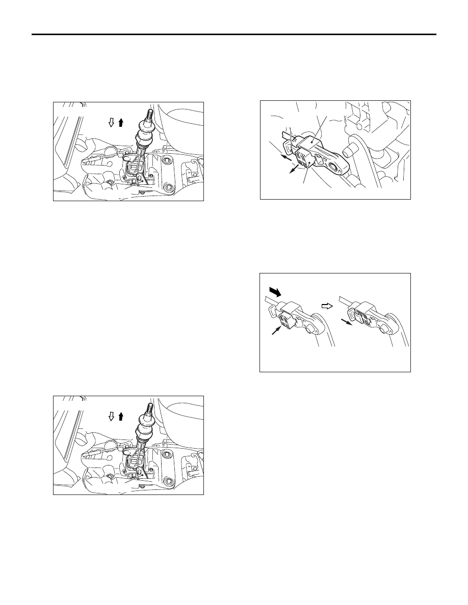
>>C<< SELECT CABLE CONNECTION
(SHIFT LEVER SIDE) INSTALLATION
1. Move the shift lever until it contacts the 5-speed or
6-speed stopper to stabilize the shift cable at the
shift lever.
2. Release the shift lever, and install the select cable
(at the shift lever side) to the select lever while the
lever is at the neutral position.
3. Check that the shift cable (shift lever side) and the
select cable (shift lever side) are installed
securely, and move the shift lever to all shift
positions.
4. If the shift lever cannot be moved to the shift
positions, adjustment the select cable.
SELECT CABLE (SHIFT LEVER SIDE)
ADJUSTMENT
M1221013300013
Place the shift lever to the neutral position .
1. Remove the front floor console.
2. Remove the select cable from the select lever.
3. Move the shift lever until it hits the stopper at the
6th gear side.
4. Release the shift lever to place it to the neutral
position.
5. Move the lock clip of the select cable towards the
arrowed direction in the figure, and pull the fixing
clip.
6. Install the select cable to the select lever, taking
care not to move the shift lever from the neutral
position.
7. Pulling the select cable slightly towards the cabin
side, press in the fixing clip of the select cable.
Then, return the lock clip back to the original
state.
8. Move the shift lever to all shift positions.
NOTE: If the shift lever cannot be moved to each
position or is difficult to move, repeat from step 3
to step 9.
9. Install the front floor console.
AC211351AC
Select lever
Neutral position
5th gear, 6th gear direction
AC211351AC
Select lever
Neutral position
5th gear, 6th gear direction
AC211247AD
Select cable
Lock clip
Fixing clip
AC211248
Fixing clip
Lock clip
AD

TRANSFER ASSEMBLY
MANUAL TRANSMISSION (FF)
22A-160
TRANSFER ASSEMBLY
REMOVAL AND INSTALLATION
M1221003200178
CAUTION
• Always refer to GROUP 52B − Service Precautions and Airbag Modules and Clock Spring before
removing the steering wheel and airbag module assembly.
• If the Brembo brake caliper is used, be careful not to hit parts and tools against the caliper when
servicing because the paint of the caliper may delaminate.
• *: Indicates parts which should be initially tightened, and then fully tightened after placing the
vehicle horizontally and loading the full weight of the engine on the vehicle body.
Pre-removal and Post-installation Operation
• Steering Wheel Removal and Installation (Refer to
GROUP 37
− Steering Wheel
• Under Cover Removal and Installation (Refer to GROUP
51
− Front Bumper
).
• Steering Shaft Cover Removal and Installation (Refer to
GROUP 37
− Steering Clumn shaft
).
• Steering Gear and Joint Connection Removal and Instal-
lation (Refer to GROUP 37
− Steering Clumn shaft
• Front Axle Crossmember Bar Removal and Installation
(Refer to GROUP 32
− Engine Roll Stopper, Centermem-
ber
).
• Front Exhaust Pipe Removal and Installation (Refer to
GROUP 15
− Exhaust Pipe and Main Muffler
• Propeller Shaft Removal and Installation (Refer to
GROUP 25 Propeller Shaft
• Output shaft Removal and Installation (Refer to GROUP
26
− Drive Shaft Assembly
• Transmission Oil Draining and Supplying (Refer to
).
• Transfer Oil Draining and Supplying (Refer to
).
• Bleeding and Hydraulic Pressure Check <ACD> (Refer to
,
). <after installation only>
• Power Steering Fluid Refilling and Bleeding (Refer to
GROUP 37
− On-vehicle Service
) <Only after
Installation>.

TRANSFER ASSEMBLY
MANUAL TRANSMISSION (FF)
22A-161
AC211381AC
2
3
4
5
6
7
49 ± 10 N·m
167 ± 9 N·m
1
54 ± 5 N·m*
7
N
N
N
44 ± 5 N·m
69 ± 9 N·m
69 ± 9 N·m
54 ± 5 N·m*
167 ± 9 N·m
69 ± 10 N·m
69 ± 10 N·m
Removal steps
1.
Centremember assembly
•
Power steering return hose and
steering gear connection
•
Power steering pressure hose and
steering gear connection
2.
Rear roll stopper connecting bolt
<<
A
>>
3.
Front axle No.1 crossmember
assembly
4.
Pressure hose connection
5.
Gasket
<<
B
>>
6.
Transfer assembly
7.
O-ring
Removal steps (Continued)

TRANSFER ASSEMBLY
MANUAL TRANSMISSION (FF)
22A-162
REMOVAL SERVICE POINTS
<<A>> FRONT AXLE NO.1 CROSSMEM-
BER ASSEMBLY REMOVAL
Support the front axle No.1 crossmember assembly
with a transmission jack, and remove the crossmem-
ber mounting bolts and the front axle No.1 cross-
member assembly.
<<B>> TRANSFER ASSEMBLY REMOVAL
Support the transfer assembly with a transmission
jack, and remove the transfer mounting bolts and the
transfer assembly.
AC211732
AC
Transmission jack
Front axle No.1
crossmember assembly
AC211733
AC
Transmission jack
Transfer assembly
Нет комментариевНе стесняйтесь поделиться с нами вашим ценным мнением.
Текст