Mitsubishi Lancer Evolution IX. Manual — part 372
51-1
GROUP 51
CONTENTS
FRONT BUMPER ASSEMBLY . . . . .
ADHESIVE . . . . . . . . . . . . . . . . . . . . . . . . .
REMOVAL AND INSTALLATION . . . . . . . .
DISASSEMBLY AND REASSEMBLY. . . . .
REAR BUMPER ASSEMBLY . . . . . .
REMOVAL AND INSTALLATION . . . . . . . .
DISASSEMBLY AND REASSEMBLY. . . . .
SIDE AIR DAM . . . . . . . . . . . . . . . . . .
ADHESIVE . . . . . . . . . . . . . . . . . . . . . . . . .
REMOVAL AND INSTALLATION . . . . . . . .
GARNISHES AND MOULDINGS. . . .
SPECIAL TOOL . . . . . . . . . . . . . . . . . . . . .
REMOVAL AND INSTALLATION . . . . . . . .
DOOR SASH TAPE . . . . . . . . . . . . . .
SPECIAL TOOL . . . . . . . . . . . . . . . . . . . . .
DOOR SASH TAPE . . . . . . . . . . . . . . . . . .
REMOVAL AND INSTALLATION . . . . . . . .
REAR SPOILER. . . . . . . . . . . . . . . . .
ADHESIVE . . . . . . . . . . . . . . . . . . . . . . . . .
REMOVAL AND INSTALLATION . . . . . . . .
WINDSHIELD WIPER AND WASHER
SERVICE SPECIFICATION . . . . . . . . . . . .
SPECIAL TOOLS . . . . . . . . . . . . . . . . . . . .
TROUBLESHOOTING . . . . . . . . . . . . . . . .
ON-VEHICLE SERVICE . . . . . . . . . . . . . . .
WINDSHIELD INTERMITTENT WIPER
INSPECTION. . . . . . . . . . . . . . . . . . . . . . . .
WINDSHIELD WIPER . . . . . . . . . . . . . . . . .
REMOVAL AND INSTALLATION . . . . . . . .
INSPECTION. . . . . . . . . . . . . . . . . . . . . . . .
WINDSHIELD WASHER . . . . . . . . . . . . . . .
REMOVAL AND INSTALLATION . . . . . . . .
INSPECTION. . . . . . . . . . . . . . . . . . . . . . . .
MARK . . . . . . . . . . . . . . . . . . . . . . . . .
REMOVAL AND INSTALLATION . . . . . . . .
DOOR MIRROR . . . . . . . . . . . . . . . . .
SERVICE SPECIFICATION . . . . . . . . . . . .
SPECIAL TOOL. . . . . . . . . . . . . . . . . . . . . .
TROUBLESHOOTING . . . . . . . . . . . . . . . .
DIAGNOSIS TROUBLESHOOTING FLOW
TROUBLE SYMPTOM CHART . . . . . . . . . .
SYMPTOM PROCEDURES . . . . . . . . . . . .
DOOR MIRROR . . . . . . . . . . . . . . . . . . . . .
REMOVAL AND INSTALLATION . . . . . . . .
FRONT BUMPER ASSEMBLY
EXTERIOR
51-2
FRONT BUMPER ASSEMBLY
ADHESIVE
M1511000501195
Item
Specification
Front three-diamond mark
Double-sided tape: Generic products
0.8 mm thickness
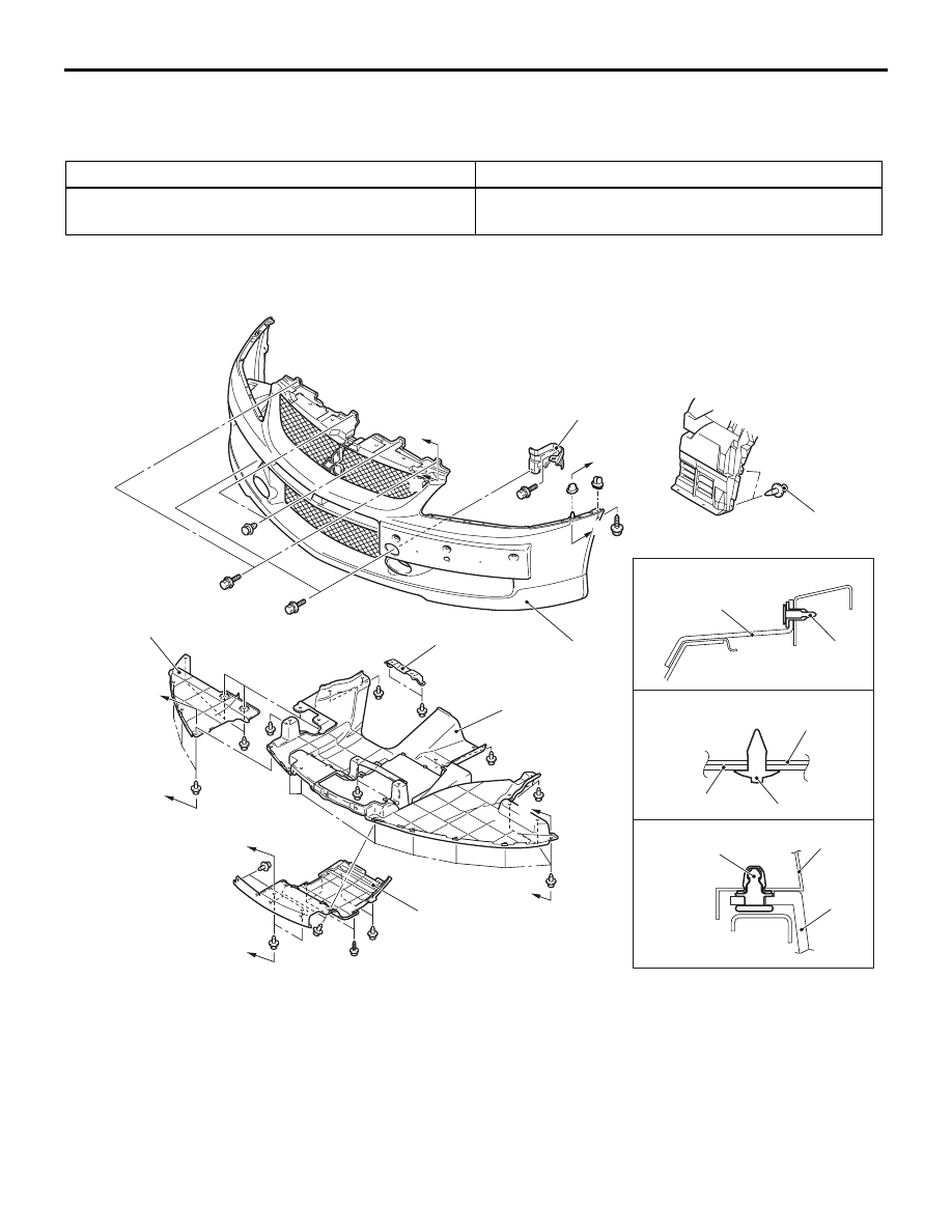
REMOVAL AND INSTALLATION
M1511001401113
AC407353
AC504541
2
1
4
5
6
6
6
4
1, 2
AB
7
Section C – C
Section B – B
Clip
Fender
Section A – A
Clip
Clip
B
B
B
B
B
B
C
A
A
3
C
Removal steps
1. Side under cover
2. Centre under cover
3. Under cover centre bracket
4. Front under cover
5. Splash shield mounting clips
•
Water spray hose connection
6. Front bumper assembly
7. Front bumper stay assembly
Removal steps (Continued)

FRONT BUMPER ASSEMBLY
EXTERIOR
51-3
DISASSEMBLY AND REASSEMBLY
M1511001601117
AC407316
AC309968
AC504539
AC504538
AB
8
9
16
7
14
11
17
18
19
5
5
4
22
1
C
C
Section C – C
Section B – B
View A
B
A
B
B
Clip
21
12
Double-sided tape: Generic products
0.8 mm thickness
1
6
3
N
2
N
12
10
10
N
13
15
15
N
13
N
20
21
Screw
Hook
Disassembly steps
1. Front three-diamond mark
2. Front bumper nut
3. Front licence plate garnish
4. Front bumper cover A
5. Front bumper cover B
6. Air dam skirt panel
7. Clip A
8. Front bumper centre net
9. Front bumper lower plate
10. Grille side cover
11. Front bumper upper plate
12. Front bumper upper support
13. Clip B
14. Air intake cover
15. Front bumper net
<<
A
>> >>
A
<< 16. Rivets
17. Bumper side net (LH)
18. Oil cooler duct (RH)
19. Bumper side net (RH)
20. Front bumper side plate
21. Front bumper upper reinforcement
22. Front bumper face
Disassembly steps (Continued)

FRONT BUMPER ASSEMBLY
EXTERIOR
51-4
DISASSEMBLY SERVICE POINT
<<A>> RIVETS REMOVAL
AC100411AB
Rivet
Drill
Bumper face
Use a drill (4.0 mm) to make a hole in the rivet to
break it, and then remove the rivet.
ASSEMBLY SERVICE POINT
>>A<< RIVETS ASSEMBLY
AC305178AC
1
2
3
4
Portion A
Rivet
Rivet tool
Flange
Rivet
Front bumper
side plate
Rivet tool
Front bumper
face
Front bumper face
Use the rivet tool shown in the illustration to attach
the rivet by the following procedures.
1. Insert the rivet into the front bumper face and front
bumper side plate.
2. Place the rivet tool over portion A of the rivet.
3. While pushing the flange surface of the rivet with
the rivet tool, press the handle of the tool.
4. The thin part of portion A is cut out and the rivet is
held in position.
Нет комментариевНе стесняйтесь поделиться с нами вашим ценным мнением.
Текст