Mitsubishi Lancer Evolution IX. Manual — part 649
SRS CONTROL UNIT (SRS-ECU)
SUPPLEMENTAL RESTRAINT SYSTEM (SRS)
52B-109
SRS CONTROL UNIT (SRS-ECU)
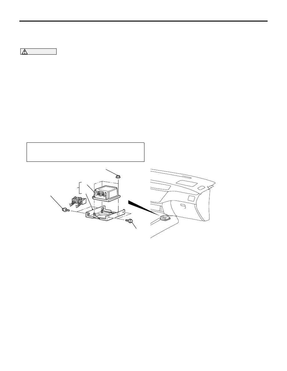
REMOVAL AND INSTALLATION
M1524002100491
WARNING
•
Disconnect the negative battery terminal and wait for 60 seconds or more before starting
work. Furthermore, the disconnected battery terminal should be covered with tape to
insulate it.
•
Never attempt to disassemble or repair the SRS-ECU. If faulty, replace it.
•
Do not drop or subject the SRS-ECU to impact or vibration. If denting, cracking, deforma-
tion, or rust are discovered in the SRS-ECU, replace it with a new SRS-ECU. Discard the
old one.
•
After deployment of an air bag, replace the SRS-ECU with a new one.
•
Never use an ohmmeter on or near the SRS-ECU, and use only the special test equipment
described on
.
Pre-removal Operation
• Turn the ignition switch to the "LOCK" (OFF) position.
• Disconnect the Negative Battery Terminal.
AC311091
5.0 ± 1.0 N·m
5.0 ± 1.0 N·m
5.0 ± 1.0 N·m
1
2
3
AB
Removal steps
•
Front floor console (Refer to
GROUP 52A
− Front floor console
assembly
1.
SRS-ECU and SRS-ECU bracket
2.
SRS-ECU
3.
SRS-ECU bracket
Installation steps
3.
SRS-ECU bracket
>>
A
2.
SRS-ECU
1.
SRS-ECU and SRS-ECU bracket
•
Front floor console (Refer to
GROUP 52A
− Front floor console
assembly
•
Negative battery cable connection
>>
B
•
Post-installation inspection
DRIVER'S AND PASSENGER'S (FRONT) AIR BAG MODULES AND CLOCK SPRING
SUPPLEMENTAL RESTRAINT SYSTEM (SRS)
52B-110
INSTALLATION SERVICE POINTS
>>A<< SRS-ECU INSTALLATION
WARNING
The SRS may not activate if SRS-ECU is not
installed properly.
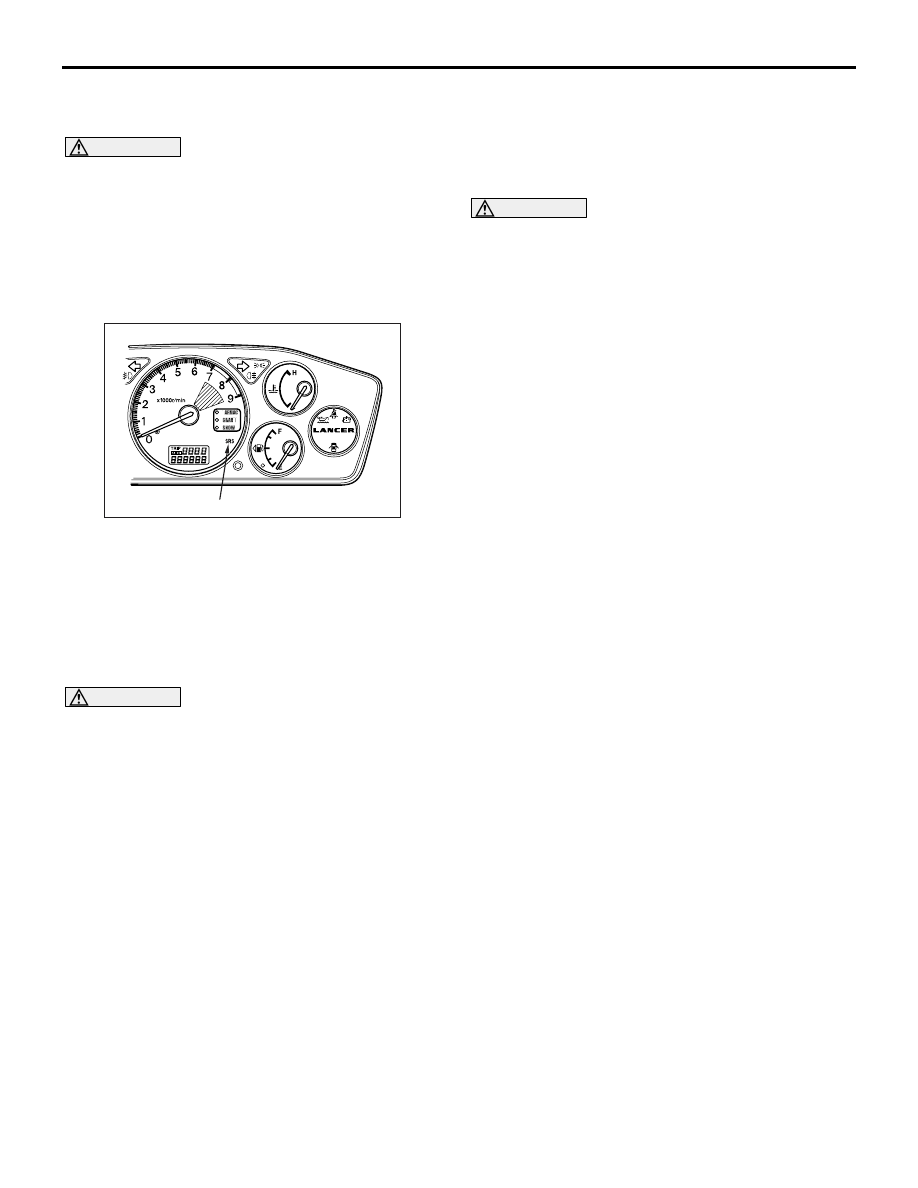
>>B<< POST-INSTALLATION
INSPECTION
1. Connect the negative battery cable.
2. Turn the ignition switch to "ON" position.
3. Does the SRS warning lamp illuminate for about 7
seconds and then goes out?
4. If no, refer to troubleshooting (Refer to
).
INSPECTION
M1524002200324
WARNING
If any problems are found, replace the
SRS-ECU.
• Check the SRS-ECU and brackets for dents,
cracks or deformation.
• Check the SRS-ECU connector for damage, and
the terminals for deformation.
NOTE: For the checks other than the items above,
refer to "Troubleshooting" (Refer to
).
DRIVER'S AND PASSENGER'S (FRONT) AIR BAG
MODULES AND CLOCK SPRING
REMOVAL AND INSTALLATION
M1524014500269
WARNING
•
Disconnect the negative battery terminal and wait for 60 seconds or more before starting
work. Furthermore, the disconnected battery terminal should be covered with tape to
insulate it.
•
Never attempt to disassemble or repair the air bag modules or clock spring. If faulty,
replace it.
•
Do not drop the air bag modules or clock spring or allow contact with water, grease or oil.
Replace it if a dent, crack, deformation or rust is detected.
•
The air bag modules should be stored on a flat surface is facing upward. Do not place
anything on top of it.
•
Do not expose the air bag modules to temperatures over 93
°
C.
•
After deployment of an air bag, replace the clock spring with a new one.
•
Wear gloves and safety glasses when handling air bags that have already deployed.
•
An undeployed air bag module should only be disposed of in accordance with the proce-
dures (Refer to
).
AC311044
SRS warning lamp
AB

DRIVER'S AND PASSENGER'S (FRONT) AIR BAG MODULES AND CLOCK SPRING
SUPPLEMENTAL RESTRAINT SYSTEM (SRS)
52B-111
<DRIVER’S AIR BAG MODULE AND CLOCK SPRING>
AC211864
AC504607
2
1
0.69 ± 0.15 N·m
3
50 ± 5 N·m
Section A - A
Section B - B
Claw
Claw
NOTE
: Claw positions
A
A
B
B
Column switch
5
AB
Driver’s air bag module removal
steps
<<
A
>>
1. Cover
<<
B
>>
2. Steering wheel and driver’s air bag
module assembly
Clock spring removal steps
<<
A
>>
1. Cover
<<
B
>>
2. Steering wheel and driver’s air bag
module assembly
•
Lower column cover (Refer to
GROUP 37
− Steering shaft
).
<<
C
>>
3. Clock spring
Driver’s air bag module installation
steps
>>
A
<< • Pre-installation inspection
>>
C
<< 2. Steering wheel and driver’s air bag
module assembly
1. Cover
•
Negative battery cable connection
>>
D
<< • Post-installation inspection
Clock spring installation steps
>>
A
<< • Pre-installation inspection
>>
B
<< 3. Clock spring
•
Lower column cover (Refer to
GROUP 37
− Steering shaft
>>
C
<< 2. Steering wheel and driver’s air bag
module assembly
1. Cover
•
Negative battery cable connection
>>
D
<< • Post-installation inspection
Driver’s air bag module installation
steps (Continued)

DRIVER'S AND PASSENGER'S (FRONT) AIR BAG MODULES AND CLOCK SPRING
SUPPLEMENTAL RESTRAINT SYSTEM (SRS)
52B-112
<PASSENGER'S (FRONT) AIR BAG MODULE>
REMOVAL SERVICE POINTS
<<A>> COVER REMOVAL
Insert the special tool ornament remover
(MB990784) as shown in the illustration to remove
the cover.
AC304946AB
1
Passenger’s (front) removal steps
•
Instrument panel (Refer to GROUP
52A
− Instrument panel
<<
D
>>
1. Passenger’s (front) air bag module
Passenger’s (front) installation
steps
>>
A
<< • Pre-installation inspection
1. Passenger’s (front) air bag module
•
Instrument panel (Refer to GROUP
52A
− Instrument panel
•
Negative battery cable connection
>>
D
<< • Post-installation inspection
AC211761AB
MB990784
Нет комментариевНе стесняйтесь поделиться с нами вашим ценным мнением.
Текст