Mitsubishi Lancer Evolution IX. Manual — part 647

TROUBLESHOOTING
SUPPLEMENTAL RESTRAINT SYSTEM (SRS)
52B-101
NOTE:
Prior to the wiring harness inspection, check junction
block connectors C-211 and C-214, and repair if nec-
essary.
Q: Is the check result normal?
YES :
An intermittent malfunction is suspected
(Refer to GROUP 00
− How to Use
Troubleshooting/Inspection Service Points
).
NO :
Repair the harness wires.
STEP 7. Retest the system.
Q: Does the M.U.T.-II/III communicate normally with
the SRS system?
YES :
An intermittent malfunction is suspected
(Refer to GROUP 00
− How to Use
Troubleshooting/Inspection Service Points
).
NO :
Replace the SRS-ECU (Refer to
).
AC303823
Junction block (front view)
Connectors: C-211, C-214
C-214
C-211
AV
<RHD>
C-211
Harness side
(front view)
C-214
AC303809
Junction block (front view)
Connectors: C-211, C-214
C-211
Harness side
(front view)
C-214
C-211
AY
<LHD>
C-214

POST-COLLISION DIAGNOSIS
SUPPLEMENTAL RESTRAINT SYSTEM (SRS)
52B-102
POST-COLLISION DIAGNOSIS
M1524001100692
Whether or not the air bags have deployed, check
and service the vehicle after collision as follows:
SRS-ECU MEMORY CHECK
CAUTION
Refer to that the ignition switch is "LOCK" (OFF)
when connecting or disconnecting M.U.T.-II/III.
1. Connect the M.U.T.-II/III to the diagnosis
connector (Refer to GROUP 00
− How to Use
Troubleshooting/Inspection Service Points
2. Read (and write down) all displayed diagnosis
NOTE: If battery power supply has been shut
down by the collision, the M.U.T.-II/III cannot com-
municate with the SRS-ECU. Check and, repair if
necessary, the instrument panel wiring harness
before the next job.
3. Use the M.U.T.-II/III to read the data list (how long
trouble(s) have continued and how often memory
have been erased).
AC304777
Steering shaft
AB
MB991502
<Using the M.U.T.-II>
AC211686
MB991911
16-PIN
MB991827
MB991824
AE
<Using the M.U.T.-III>

POST-COLLISION DIAGNOSIS
SUPPLEMENTAL RESTRAINT SYSTEM (SRS)
52B-103
Data list
4. Erase the diagnosis codes and after waiting 5
seconds or more read (and write down) all
displayed diagnosis codes.
REPAIR PROCEDURE
WHEN FRONT AIR BAGS DEPLOY IN A
COLLISION
1. Replace the following parts with new ones.
• Front impact sensor (Refer to
• SRS-ECU (Refer to
• Driver’s and passenger’s (front) air bag modules
(Refer to
• Seat belt with pre-tensioner (Refer to
).
• Instrument panel (Refer to GROUP 52A − Instru-
ment Panel Assembly
2. Check the following parts and replace if there are
any malfunctions.
).
• Steering wheel, steering column and shaft
assembly
(1) Check the wiring harness (built into the
steering wheel) and connectors for damage,
and terminals for deformation.
(2) Install the air bag module to check fit or
alignment with the steering wheel.
(3) Check the steering wheel for noise, binds or
difficult operation and excessive free play.
(4) Check the steering column shaft shock
absorbing mechanism (Refer to GROUP 37
−
).
3. Check the harness for binding, connectors for
damage, poor connections, and terminals for
deformation (Refer to
WHEN AIR BAGS DO NOT DEPLOY IN
LOW-SPEED COLLISION
Check the SRS components. If visible damage such
as dents, cracks, or deformation are found on the
SRS components, replace them with new ones. Con-
cerning parts removed for inspection, replacement
with new parts and cautions in working refer to
FRONT IMPACT SENSOR
1. Check the radiator support panel for distortion and
rust.
2. Check the front impact sensor for dents, cracks,
deformation or rust.
3. Check the front impact sensor wiring harness for
binding, check the connector for damage, and
check the terminals for deformation.
SRS-ECU
No
Data List Item
Applicability
92
Number indicating how often the memory is
cleared
Maximum time to be stored: 250 times
93
How long a problem has lasted (How long it
takes from the occurrence of the problem till
the first air bag squib igniting signal)
Maximum time to be stored: 9,999 minutes
(approximately 7 days)
94
How long a problem has lasted (How long it
takes from the first air bag squib igniting
signal till now).
AC208855
Front impact
sensor
AF
Battery
AC300582
SRS-ECU
AB
POST-COLLISION DIAGNOSIS
SUPPLEMENTAL RESTRAINT SYSTEM (SRS)
52B-104
1. Check the SRS-ECU case and brackets for dents,
cracks or deformation.
2. Check the connector for damage, and the
terminals for deformation.
3. Check the SRS-ECU and bracket for installation
condition.
AIR BAG MODULES
1. Check the pad cover for dents, cracks or
deformation.
2. Check the connector for damage, terminals
deformities, and the harness for binding.
3. Check the air bag inflator case for dents, cracks or
deformities.
4. Check the air bag modules for proper installation.
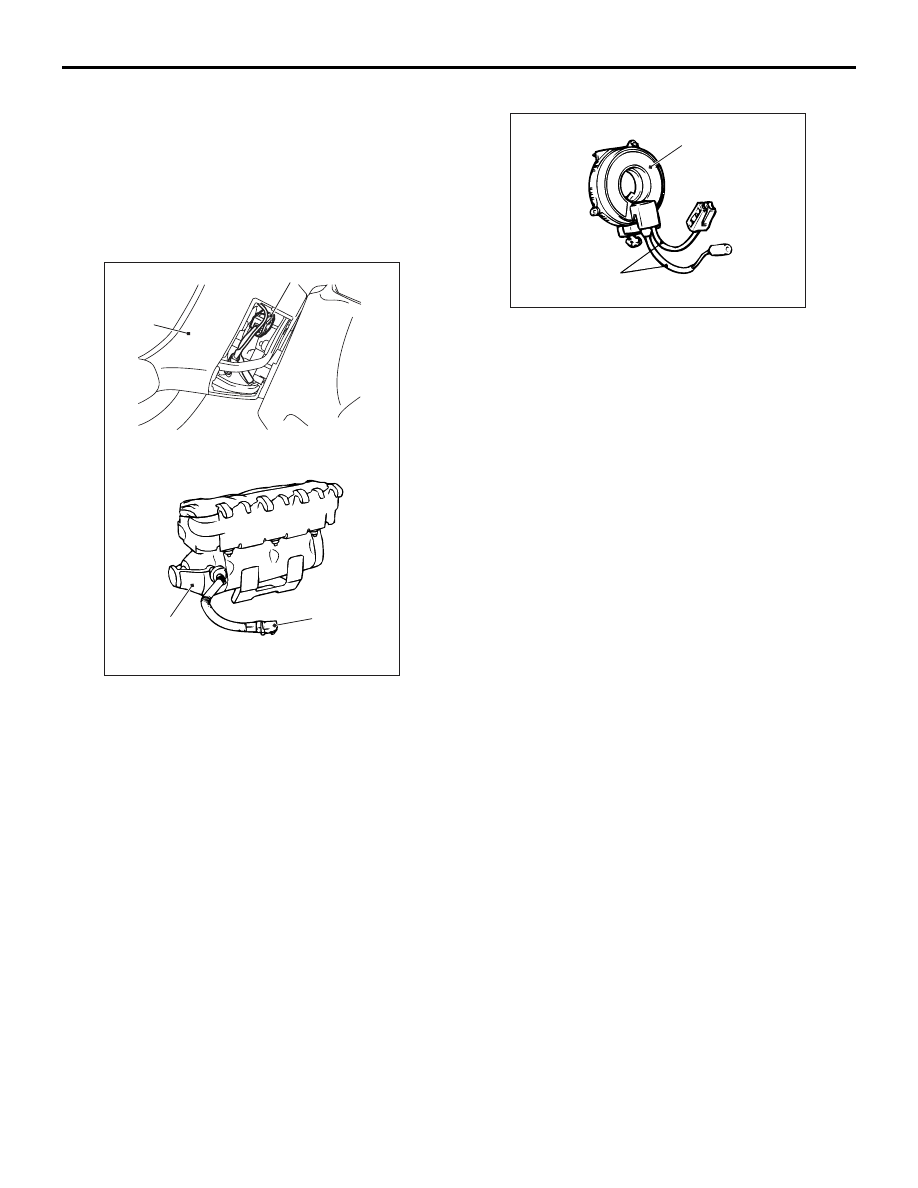
CLOCK SPRING
1. Check the clock spring connectors and protective
tube for damage, and the terminals for
deformation.
2. Visually check the case for damage.
STEERING WHEEL, STEERING COLUMN
AND SHAFT ASSEMBLY
1. Check the wiring harness (built into the steering
wheel) and the connectors for damage, and the
terminals for deformation.
2. Install the air bag module to check fit or alignment
with the steering wheel.
3. Check the steering wheel for noise, binding or
difficult operation and excessive free play.
4. Check the steering column shaft shock absorbing
mechanism (Refer to GROUP 37
− On-vehicle
Service
).
SEAT BELT WITH PRE-TENSIONER
1. Check the seat belt for damage or deformation.
2. Check the seat belt with pre-tensioner for cracks
or deformation.
3. Check that the unit is installed correctly to the
vehicle body.
HARNESS CONNECTOR (INSTRUMENT
PANEL WIRING HARNESS AND FLOOR
WIRING HARNESS, ROOF WIRING
HARNESS)
Check harnesses for binding, connectors for damage
and terminals for deformation (Refer to
).
AC006205
AC311067
AC304700
Steering
wheel
AC
Inflator case
Connector
<Driver's side>
Connector
<Front passenger's side>
AC300585AB
Case
Protective tubes
Нет комментариевНе стесняйтесь поделиться с нами вашим ценным мнением.
Текст