Mitsubishi Lancer Evolution IX. Manual — part 476
TROUBLESHOOTING
MULTIPORT FUEL INJECTION (MPI)
13A-379
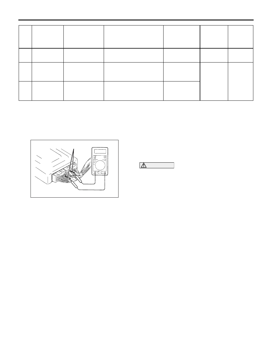
CHECK AT THE ENGINE-ECU
TERMINALS
M1131153500744
TERMINAL VOLTAGE CHECK CHART
1. Connect a needle-nosed wire probe to a voltmeter
probe.
2. Insert the needle-nosed wire probe into each of
the engine-ECU connector terminals from the wire
side, and measure the voltage while referring to
the check chart.
NOTE:
.
1. Make the voltage measurement with the
engine-ECU connector connected.
2. You may find it convenient to pull out the
engine-ECU to make it easier to reach the
connector terminals.
3. The checks can be carried out off the order
given in the chart.
CAUTION
Short-circuiting the positive (+) probe between a
connector terminal and earth could damage the
vehicle wiring, the sensor, engine-ECU or all of
them. Be careful to prevent this!
3. If voltmeter shows any division from standard
value, check the corresponding sensor, actuator
and related electrical wiring, then repair or
replace.
4. After repair or replacement, recheck with the
voltmeter to confirm that the repair has corrected
the problem.
21
Fan
controller
Actuate fan
motor
• Ignition switch: "ON"
• A/C switch: ON
Fan motor is
rotated
Procedure
No. 25
37
Condenser
fan (high)
Condenser fan
motor is driven.
Ignition switch: "ON"
Fan motor
rotates at high
speed
Procedure
No. 26
38
Condenser
fan (low)
Condenser fan
motor is driven.
Ignition switch: "ON"
Fan motor
rotates at low
speed
Item
No.
Inspection
item
Drive content
Inspection conditions
Normal
condition
Code No.
/Inspection
procedure
No.
Reference
page
AK201749AB
Needle-nosed wire probe

TROUBLESHOOTING
MULTIPORT FUEL INJECTION (MPI)
13A-380
Engine-ECU Connector Terminal Arrangement
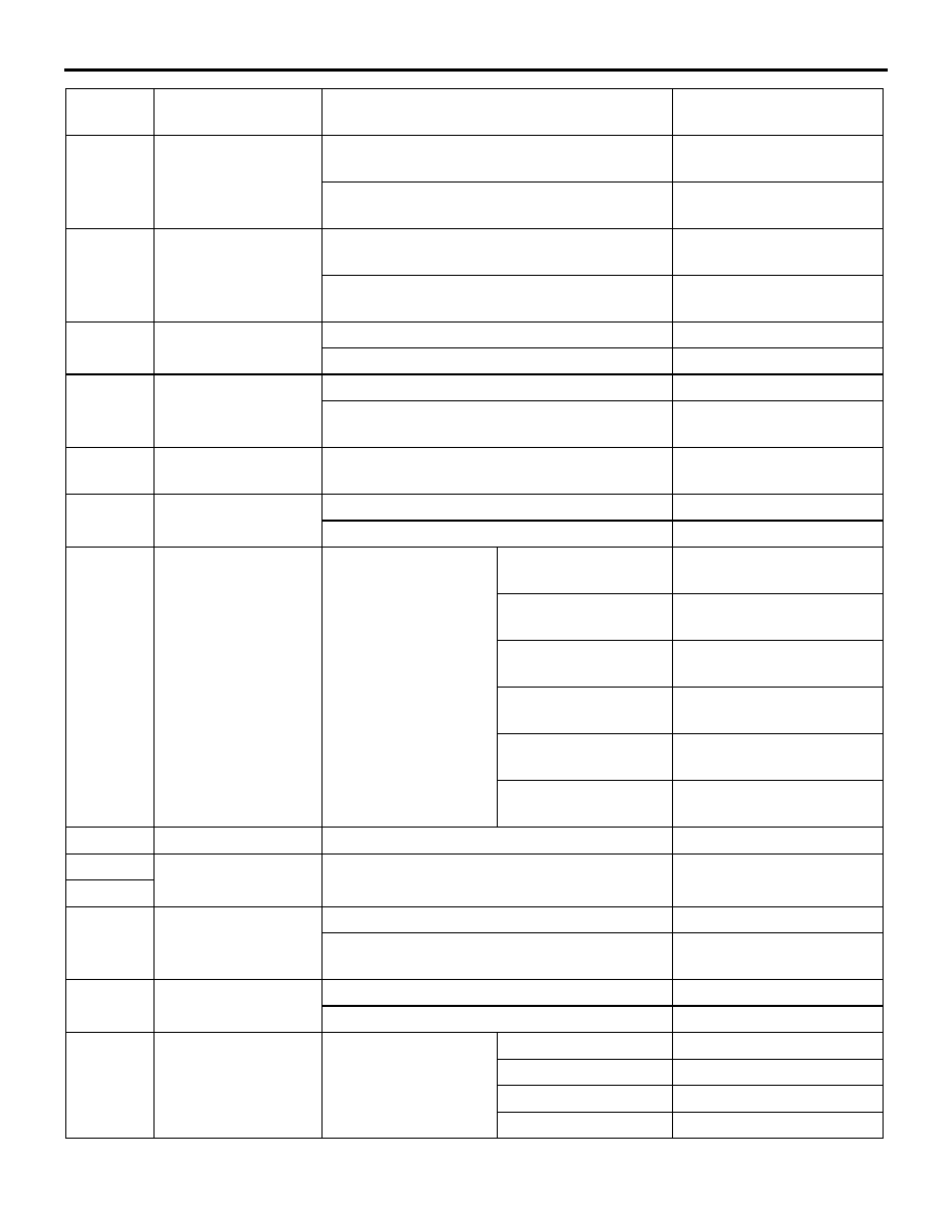
Terminal
No.
Check item
Check condition (Engine condition)
Normal condition
1
No. 1 injector
While engine is idling after having warmed
up, suddenly depress the accelerator pedal.
From 11
− 14 V,
momentarily drops slightly
9
No. 2 injector
24
No. 3 injector
2
No. 4 injector
3
Oxygen sensor
heater (front)
Engine: Idling after warming up
1 V or less
Engine r/min: 5,000 r/min
System voltage
6
EGR control
solenoid valve
Ignition switch: "ON"
System Voltage
While engine is idling, suddenly depress the
accelerator pedal.
From system voltage,
momentarily drops
8
Alternator G terminal
• Engine: Warm, idle (radiator fan: OFF)
• Headlamp: OFF → ON
• Stop lamp: OFF → ON
• Rear defogger switch: OFF → ON
Voltage increases by 0.2
−
3.5 V
11
Ignition coil
− No. 1,
No. 4
Engine r/min: 3,000 r/min
0.3
− 3.0 V
12
Ignition coil
− No. 2,
No. 3
14
Stepper motor coil
<A1>
• Engine: Soon after the warmed up engine
is started
• A/C switch: OFF → ON (A/C compressor
is operating)
• Headlight switch: OFF → ON
System voltage
⇔ 1V or
less (Changes repeatedly)
28
Stepper motor coil
<A2>
15
Stepper motor coil
<B1>
29
Stepper motor coil
<B2>
16
Purge control
solenoid valve
Ignition switch: "ON"
System voltage
Running at 3,500 r/min while engine is
warming up after having been started.
1 V or less
18
Fan controller
Radiator fan is not operating
0
− 0.3 V
Radiator fan is operating
0.7 V or more
19
Air flow sensor reset
signal
Engine: Idle speed
0
− 1 V
Engine r/min: 3,000 r/min
6
− 9 V
20
A/C relay
• Engine: Idle speed
• A/C switch: OFF → ON (A/C compressor
is operating)
System voltage or
Momentarily 6 V or more
→ 1 V or less
21
Fuel pump relay 2
Ignition switch: "ON"
System voltage
Engine: Idle speed
1 V or less
22
Engine warning lamp Ignition switch: "LOCK" (OFF)
→ "ON"
1 V or less
→ System
voltage (After several
seconds have elapsed)
26
Oxygen sensor
heater (rear)
Engine: Idling after warming up
1 V or less
Engine: Racing
System voltage
TROUBLESHOOTING
MULTIPORT FUEL INJECTION (MPI)
13A-381
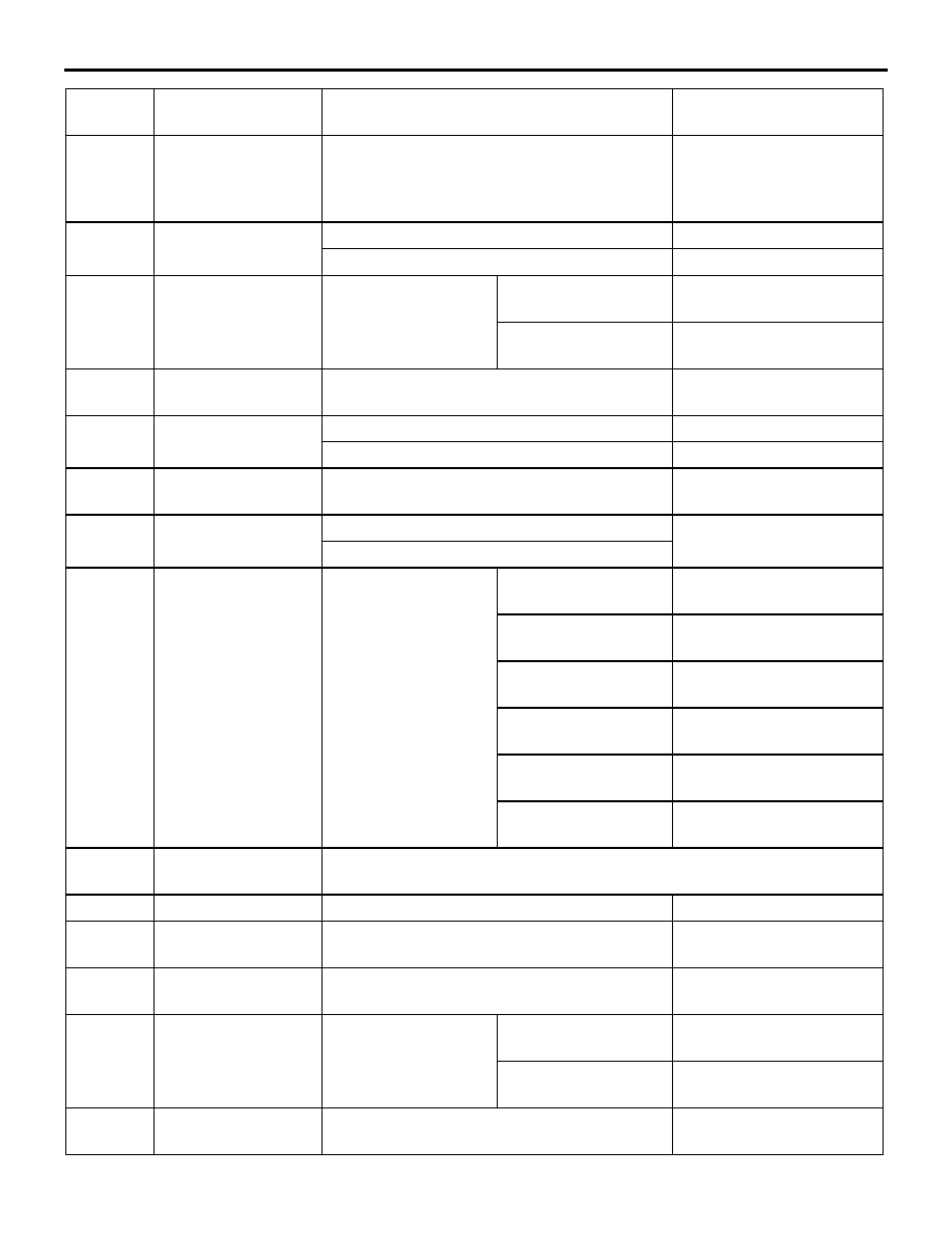
30
Condenser fan
motor relay (high)
Fan inactive state (Engine coolant
temperature: 90
°C or less)
System voltage
Fan high-speed rotation state (Engine
coolant temperature: 105
°C or less)
1 V or less
31
Condenser fan
motor relay (low)
Fan inactive state (Engine coolant
temperature: 90
°C or less)
System voltage
Fan low-speed rotation state (Engine coolant
temperature: 95
− 100°C or less)
1 V or less
33
Oil feeder control
valve
Ignition switch: "ON"
System voltage
High-load running
4.0
− 10 V
41
Waste gate solenoid
valve
Ignition switch: "ON"
System voltage
Engine: After warm-up, idle operation (When
using premium gasoline)
1 V or less
42
Sensor impressed
voltage
Ignition switch: "ON"
4.9
− 5.1 V
43
Crank angle sensor
Engine: Cranking
0.4
− 4.0 V
Engine: Idling speed
1.5
− 2.5 V
44
Engine coolant
temperature sensor
Ignition switch: "ON"
When engine coolant
temperature is
−20°C
3.9
− 4.5 V
When engine coolant
temperature is 0
°C
3.2
− 3.8 V
When engine coolant
temperature is 20
°C
2.3
− 2.9 V
When engine coolant
temperature is 40
°C
1.3
− 1.9 V
When engine coolant
temperature is 60
°C
0.7
− 1.3 V
When engine coolant
temperature is 80
°C
0.3
− 0.9 V
45
Tachometer signal
Engine r/min: 3,000 r/min
0.3
− 3.0 V
47
Power supply
Ignition switch: "ON"
System voltage
59
48
Fuel pressure
control solenoid
valve
Ignition switch: "ON"
System voltage
Engine: Cranking
→ Idle operation (within
approximately 2 minutes or less)
1 V or less
→ System
voltage
50
Exhaust camshaft
position sensor
Engine: Cranking
0.4
− 3.0 V
Engine: Idling
1.5
− 3.0 V
51
Barometric pressure
sensor
Ignition switch: "ON"
Altitude: 0 m
3.8
− 4.2 V
Altitude: 600 m
3.5
− 3.9 V
Altitude: 1,200 m
3.3
− 3.7 V
Altitude: 1,800 m
3.0
− 3.4 V
Terminal
No.
Check item
Check condition (Engine condition)
Normal condition
TROUBLESHOOTING
MULTIPORT FUEL INJECTION (MPI)
13A-382
52
Alternator FR
terminal
• Engine: Warm, idle (radiator fan: OFF)
• Headlamp: OFF → ON
• Stop lamp: OFF → ON
• Rear defogger switch: OFF → ON
Voltage decreases
53
Intake camshaft
position sensor
Engine: Cranking
0.4
− 3.0 V
Engine: Idling
1.5
− 3.0 V
54
Power steering fluid
pressure switch
Engine: Idling after
warming up
When steering wheel
is stationary
System voltage
When steering wheel
is turned
1 V or less
55
Fuel pump relay 3
While engine is idling, suddenly depress the
accelerator pedal.
Temporarily rises slightly
from 1 V or less.
57
Control relay (Power
supply)
Ignition switch: "LOCK" (OFF)
System voltage
Ignition switch: "ON"
1 V or less
60
Backup power
supply
Ignition switch: "LOCK" (OFF)
System voltage
61
Air flow sensor
Engine: Idle speed
2.2
− 3.2 V
Engine r/min: 2,500 r/min
62
Intake air
temperature sensor
Ignition switch: "ON"
When intake air
temperature is
−20°C
3.8
− 4.4 V
When intake air
temperature is 0
°C
3.2
− 3.8 V
When intake air
temperature is 20
°C
2.3
− 2.9 V
When intake air
temperature is 40
°C
1.5
− 2.1 V
When intake air
temperature is 60
°C
0.8
− 1.4 V
When intake air
temperature is 80
°C
0.4
− 1.0 V
65
A/C load signal
Refer to GROUP 55 - Troubleshooting (Inspection at the Automatic
compressor - ECU Terminal)
68
Ignition switch-ST
Engine: Cranking
8 V or more
71
Oxygen sensor
(front)
Engine: Running at 2,500 r/min after warmed
up (Check using a digital type voltmeter)
0
⇔ 0.8 V (Changes
repeatedly)
73
Oxygen sensor
(rear)
Engine: Idling after warmed up (Check using
a digital type voltmeter)
0
⇔ 0.6 V (Changes
repeatedly)
78
Throttle position
sensor
Ignition switch: "ON"
Set throttle valve to
idle Position
0.535
− 0.735 V
Fully open throttle
valve
4.4
− 5.3 V
80
Vehicle speed
sensor
• Ignition switch: "ON"
• Move the vehicle forword slowly
0
⇔ 5 V Changes
repeatedly
Terminal
No.
Check item
Check condition (Engine condition)
Normal condition
Нет комментариевНе стесняйтесь поделиться с нами вашим ценным мнением.
Текст