Mitsubishi Lancer Evolution IX. Manual — part 477

TROUBLESHOOTING
MULTIPORT FUEL INJECTION (MPI)
13A-383
CHECK CHART FOR RESISTANCE AND
CONTINUITY BETWEEN TERMINALS
1. Turn the ignition switch to "LOCK" (OFF) position.
2. Disconnect the engine-ECU connector.
3. Measure the resistance and check for continuity
between the terminals of the engine-ECU
harness-side connector while referring to the
check chart.
NOTE:
.
1. When measuring resistance and checking
continuity, a harness for checking contact pin
pressure should be used instead of inserting a
test probe.
2. Checking need not be carried out in the order
given in the chart.
CAUTION
If the terminals that should be checked are mis-
taken, or if connector terminals are not correctly
shorted to earth, damage may be caused to the
vehicle wiring, sensors, engine-ECU and/or ohm-
meter. Be careful to prevent this!
4. If the ohmmeter shows any deviation from the
standard value, check the corresponding sensor,
actuator and related electrical wiring, and the
repair or replace.
5. After repair or replacement, recheck with the
ohmmeter to confirm that the repair or
replacement has corrected the problem.
83
A/C switch
Engine: Idle speed
Turn the A/C switch
OFF
0.5 V or less
Turn the A/C switch
ON (A/C compressor
is operating)
System voltage
96
Transmission oil
temperature sensor
Ignition switch: "ON"
Transmission oil
temperature is
−20°C
3.9
− 4.5 V
Transmission oil
temperature is 0
°C
3.2
− 3.8 V
Transmission oil
temperature is 20
°C
2.3
− 2.9 V
Transmission oil
temperature is 40
°C
1.3
− 1.9 V
Transmission oil
temperature is 60
°C
0.7
− 1.3 V
Transmission oil
temperature is 80
°C
0.3
− 0.9 V
99
Ignition switch-IG
Ignition switch: "ON"
System voltage
Terminal
No.
Check item
Check condition (Engine condition)
Normal condition

TROUBLESHOOTING
MULTIPORT FUEL INJECTION (MPI)
13A-384
Engine-ECU Harness Side Connector Terminal Arrangement
Terminal
No.
Inspection item
Normal condition (Check condition)
1
− 47
No. 1 injector
2
− 3 Ω (At 20°C)
9
− 47
No. 2 injector
24
− 47
No. 3 injector
2
− 47
No. 4 injector
47
− 48
Fuel pressure control solenoid valve
28
− 36 Ω (At 20°C)
14
− 47
Stepper motor coil (A1)
26
− 33 Ω (At 20°C)
28
− 47
Stepper motor coil (A2)
15
− 47
Stepper motor coil (B1)
29
− 47
Stepper motor coil (B2)
6
− 47
EGR control solenoid valve
29
− 35 Ω (At 20°C)
16
− 47
Purge control solenoid valve
30
− 34 Ω (At 20°C)
41
− 47
Waste gate solenoid valve
29
− 35 Ω (At 20°C)
3
− 47
Oxygen sensor heater (rear)
11
− 18 Ω (At 20°C)
26
− 47
Oxygen sensor heater (front)
4.5
− 8.0 Ω (At 20°C)
33
− 47
Oil feeder control valve
6.9
− 7.9 Ω (At 20°C)
46
− Body
earth
ECU earth
Continuity (2
Ω or less)
58
− Body
earth
42
− 62
Intake air temperature sensor
13
− 17 kΩ (When intake air temperature is −20°C)
5.3
− 6.7 kΩ (When intake air temperature is 0°C)
2.3
− 3.0 kΩ (When intake air temperature is 20°C)
1.0
− 1.5 kΩ (When intake air temperature is 40°C)
0.56
− 0.76 kΩ (When intake air temperature is 60°C)
0.30
− 0.42 kΩ (When intake air temperature is 80°C)
42
− 44
Engine coolant temperature sensor
14
− 17 kΩ (When coolant temperature is −20°C)
5.1
− 6.5 kΩ (When coolant temperature is 0°C)
2.1
− 2.7 kΩ (When coolant temperature is 20°C)
0.9
− 1.3 kΩ (When coolant temperature is 40°C)
0.48
− 0.68 kΩ (When coolant temperature is 60°C)
0.26
− 0.36 kΩ (When coolant temperature is 80°C)
TROUBLESHOOTING
MULTIPORT FUEL INJECTION (MPI)
13A-385
INSPECTION PROCEDURE USING
OSCILLOSCOPE
M1131154501483
The output signals of the sensors and the conditions
of the actuation signals of the actuators can be
inspected visually by observing the waveforms on
the oscilloscope.
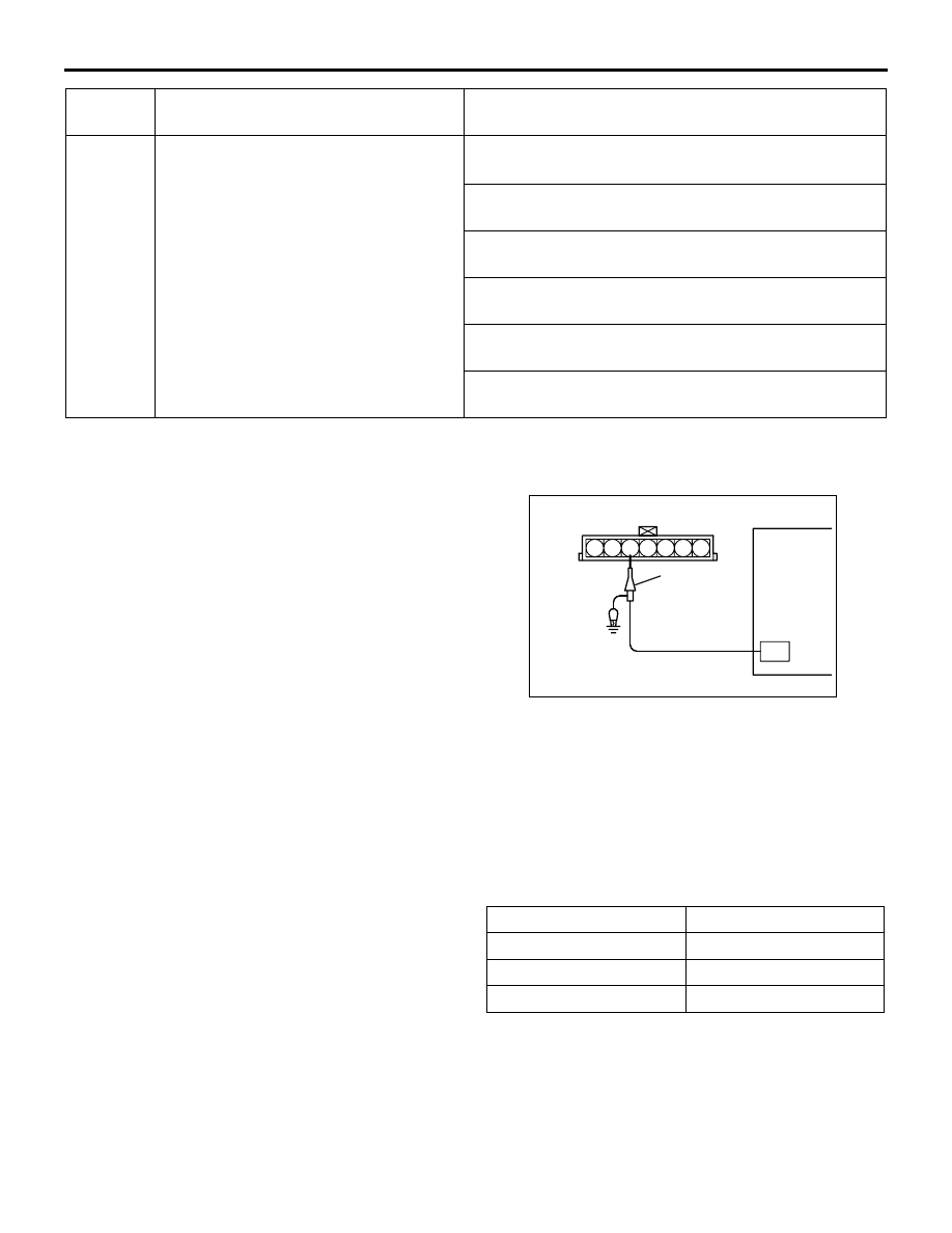
AIR FLOW SENSOR (AFS)
Measurement Method
1. Disconnect the air flow sensor connector, and
connect the special tool test harness (MB991709)
in between (All terminals should be connected).
2. Connect the oscilloscope special patterns pickup
to air flow sensor connector terminal No. 3.
Alternate Method (Test harness not available)
1. Connect the oscilloscope special patterns pickup
to engine-ECU terminal No. 61.
Standard Wave Pattern
Observation conditions
42
− 96
Transmission oil temperature sensor
14
− 17 kΩ (When transmission oil temperature is
−20°C)
5.1
− 6.5 kΩ (When transmission oil temperature is
0
°C)
2.1
− 2.7 kΩ (When transmission oil temperature is
20
°C)
0.9
− 1.3 kΩ (When transmission oil temperature is
40
°C)
0.48
− 0.68 kΩ (When transmission oil temperature is
60
°C)
0.26
− 0.36 kΩ (When transmission oil temperature is
80
°C)
Terminal
No.
Inspection item
Normal condition (Check condition)
AK000786
4 5 6
1 2 3
7
AE
Special
patterns
pickup
Oscilloscope
Function
Special patterns
Pattern height
Low
Pattern selector
Display
Engine speed
Idle

TROUBLESHOOTING
MULTIPORT FUEL INJECTION (MPI)
13A-386
Wave Pattern Observation Points
Check that cycle time T becomes shorter and the fre-
quency increases when the engine speed is
increased.
Examples of Abnormal Wave Patterns
• Example 1
Cause of problem
Sensor interface malfunction
Wave pattern characteristics
Rectangular wave pattern is output even when
the engine is not started.
• Example 2
Cause of problem
Damaged rectifier or vortex generation column
Wave pattern characteristics
Unstable wave pattern with non-uniform fre-
quency. However, when an ignition leak
occurs during acceleration, the wave pattern
will be distorted temporarily, even if the air
flow sensor is normal.
AK202334
(V)
10
T
T1
T2
0
Time
The time (cycle time) T is reduced when
the amount of intake air increases.
Standard wave pattern
Times T1 and T2 are equal.
AC
AK202335
(V)
10
T
0
Time
Observation conditions (from conditions above engine is increased by racing.)
AB
AKX01597
Нет комментариевНе стесняйтесь поделиться с нами вашим ценным мнением.
Текст