Mitsubishi Lancer Evolution IX. Manual — part 227
SYMPTOM PROCEDURES
SMART WIRING SYSTEM (SWS) USING SWS MONITOR
54C-167
Step 7. Check the wiring harness between F-18
windshield washer motor connector terminal
No.1 and body earth.
• Check the earth wires for open circuit.
Q: Is the check result normal?
YES :
The trouble can be an intermittent
malfunction (Refer to GROUP 00
− How to
Cope with Intermittent Malfunction
NO :
Repair the wiring harness.
Step 8. Connector check: A-11X front-ECU
connector
Q: Is the check result normal?
YES :
Go to Step 9.
NO :
Repair the connector.
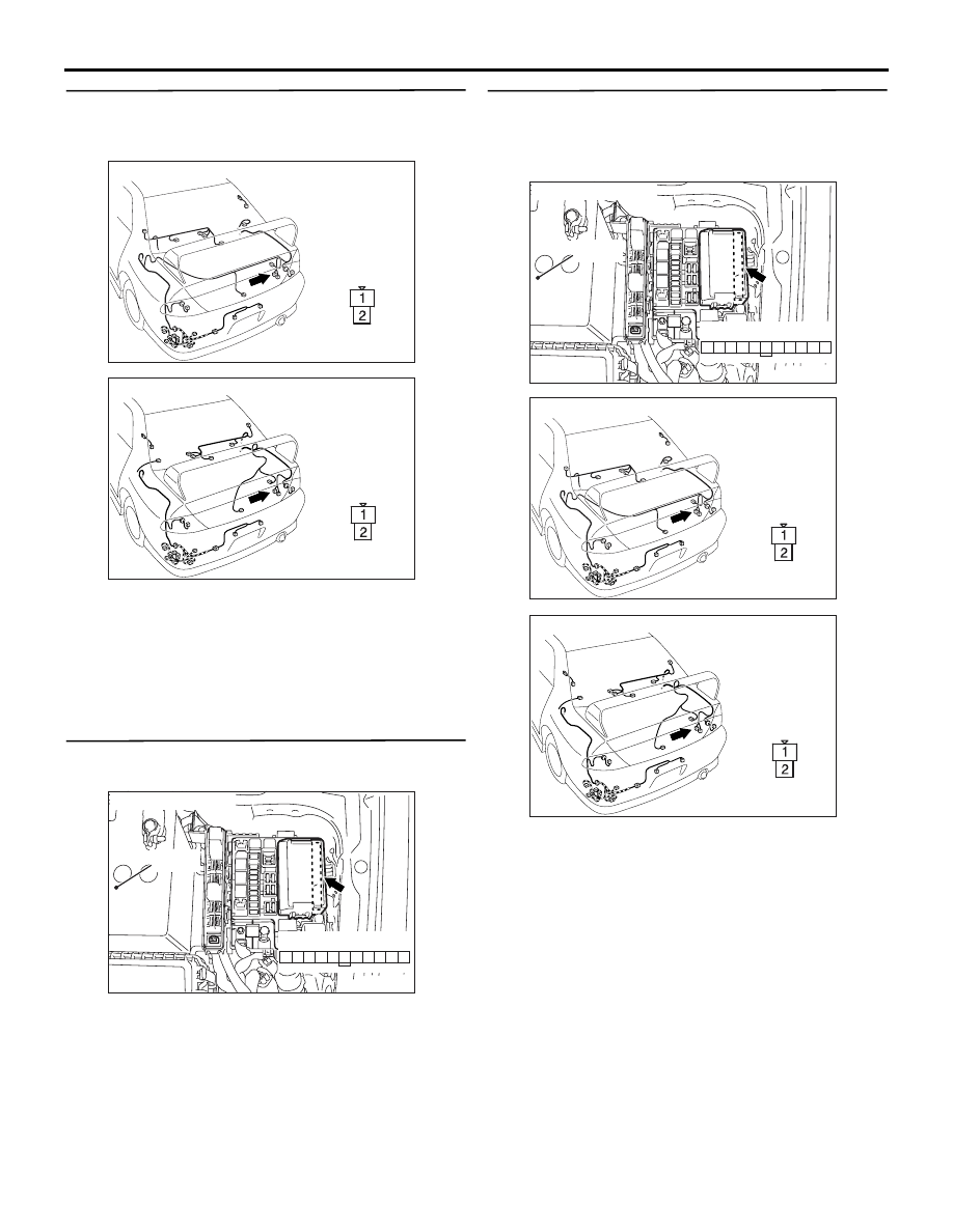
Step 9. Check the wiring harness between F-18
windshield washer motor connector terminal
No.2 and A-11X front-ECU connector terminal
No.21.
AC310467AF
Harness side
Connector: F-18 <LHD>
AC310469
AF
Harness side
Connector: F-18 <RHD>
AC310572AC
Connector: A-11X
Relay box side
Battery
29
31 30
28 27
25
26
24
21
22
23
AC310572AC
Connector: A-11X
Relay box side
Battery
29
31 30
28 27
25
26
24
21
22
23
AC310467AF
Harness side
Connector: F-18 <LHD>
AC310469
AF
Harness side
Connector: F-18 <RHD>
SYMPTOM PROCEDURES
SMART WIRING SYSTEM (SWS) USING SWS MONITOR
54C-168
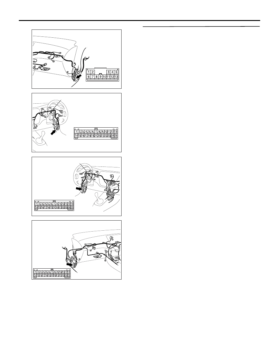
NOTE:
Prior to the wiring harness inspection, check the
intermediate connector C-113, C-129 and repair if
necessary.
• Check the power supply line to the ignition switch
(ACC) for open circuit.
Q: Is the check result normal?
YES :
Go to Step 10.
NO :
Repair the wiring harness.
Step 10. Retest the system.
The windshield washer should now work normally.
Q: Is the check result normal?
YES :
The trouble can be an intermittent
malfunction (Refer to GROUP 00
− How to
Cope with Intermittent Malfunction
NO :
Replace the front-ECU.
AC310452
Connector: C-113 <LHD>
AO
AC310456
Connector: C-113 <RHD>
AN
AC310446
Connector: C-129 <LHD>
AS
AC310454
Connector: C-129 <RHD>
AV

SYMPTOM PROCEDURES
SMART WIRING SYSTEM (SWS) USING SWS MONITOR
54C-169
IGNITION KEY CYLINDER
ILLUMINATION LAMP
INSPECTION PROCEDURE G-1: The ignition key cylinder illumination lamp does not
illuminate/extinguish normally.
CAUTION
Whenever the ECU is replaced, ensure that the
input and output signal circuits are normal.
COMMENTS ON TROUBLE SYMPTOM
The ETACS-ECU operates this function in accord-
ance with the input signals below.
• Ignition switch (IG1)
• Key reminder switch
• Driver's door switch
• Interior lamp loaded signal
If this function does not work normally, these input
signal circuit(s), the ignition key cylinder illumination
lamp or the ETACS-ECU may be defective.
POSSIBLE CAUSES
• Malfunction of the key reminder switch
• Malfunction of the driver's door switch
• Malfunction of the ignition key cylinder illumina-
tion lamp
• Malfunction of the ETACS-ECU
• Damaged harness wires and connectors
ETACS-ECU
Wire colour code
B : Black LG : Light green G : Green L : Blue W : White Y : Yellow SB : Sky blue
BR : Brown O : Orange GR : Gray R : Red P : Pink V : Violet
IGNITION KEY
CYLINDER ILLUMINATION
LAMP
KEY
REMINDER SWITCH
Ignition Key Cylinder Illumination Lamp Circuit

SYMPTOM PROCEDURES
SMART WIRING SYSTEM (SWS) USING SWS MONITOR
54C-170
DIAGNOSTIC PROCEDURE
Step 1. Check the operation of the room lamp.
Check that the room lamps illuminate and extinguish
normally.
Q: Is the check result normal?
YES :
Go to Step 2.
NO :
Refer to Inspection Procedure K-1 "The
front or rear room lamp does not illuminate
or extinguish
."
Step 2. Pulse check
Check the input signals below, which are related to
the ignition key cylinder illumination lamp.
OK: The M.U.T.-II/III sounds or the voltmeter
needle fluctuates.
Q: Is the check result normal?
All the signals are received normally. :
Go to Step
3.
The ignition switch (IG1) signal is not received. :
Refer to Inspection Procedure L-2 "The
ignition switch (IG1) signal is not received
."
The key reminder switch signal is not received. :
Refer to Inspection Procedure L-9 "The key
reminder switch signal is not received
."
The driver's door switch signal is not received. :
Refer to Inspection Procedure L-3 "The door
switch (front: LH) signal is not received <LH
drive vehicles>
Inspection Procedure L-3 "The door switch
(front: RH) signal is not received <RH drive
vehicles>
."
Step 3. Connector check: C-207 key reminder
switch connector
Q: Is the check result normal?
YES :
Go to Step 4.
NO :
Repair the defective connector.
Step 4. Check the bulb of the ignition key
cylinder illumination lamp.
Check the bulb of the ignition key cylinder illumina-
tion lamp.
Q: Is the check result normal?
YES :
Go to Step 5.
NO :
Replace the bulb of the ignition key cylinder
illumination lamp.
System switch
Check condition
Ignition switch (IG1) When turned from ACC to
ON
Key reminder switch When the inserted ignition
key is pulled out
Driver's door switch When the driver's door is
opened
AC310479
2
7 6
1
3
5 4
Connector: C-207 <LHD>
AE
Harness side
AC310481
2
7 6
1
3
5 4
Connector: C-207 <RHD>
AE
Harness side
Нет комментариевНе стесняйтесь поделиться с нами вашим ценным мнением.
Текст