Mitsubishi Lancer Evolution IX. Manual — part 225

SYMPTOM PROCEDURES
SMART WIRING SYSTEM (SWS) USING SWS MONITOR
54C-159
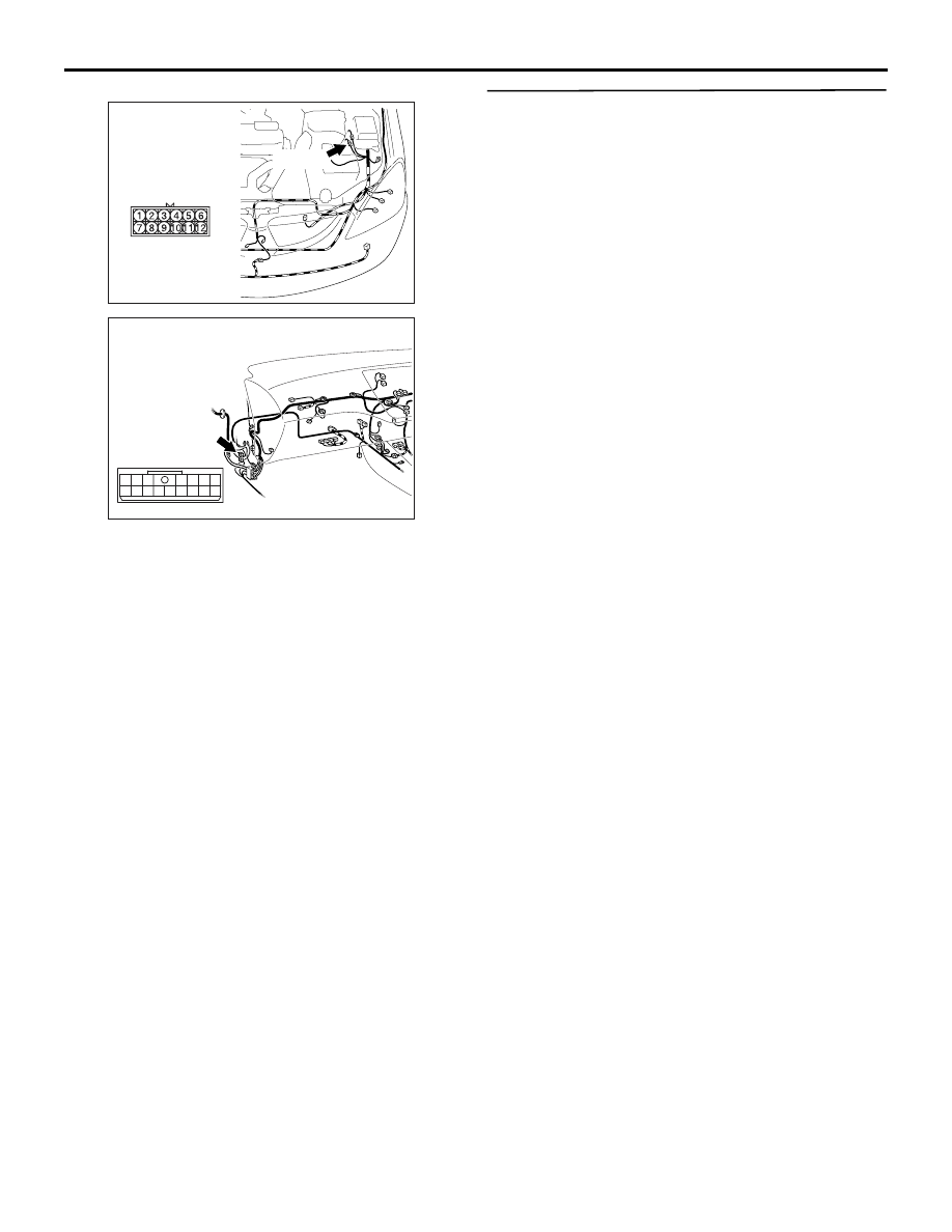
Step 8. Connector check: B-01 windshield wiper
motor connector
Q: Is the check result normal?
YES :
Go to Step 9.
NO :
Repair the defective connector.
Step 9. Check the windshield wiper motor
assembly.
Refer to GROUP 51
− Windshield wiper
.
Q: Is the check result normal?
YES :
Go to Step 10
NO :
Replace the windshield wiper motor
assembly.
Step 10. Connector check: A-11X front-ECU
connector
Q: Is the check result normal?
YES :
Go to Step 11.
NO :
Repair the defective connector.
Step 11. Check the wiring harness between A-11X
front-ECU connector terminal No.28 and B-01
windshield wiper motor connector terminal No.2.
AC310437
Connector: B-01 <LHD>
AB
Harness side
B-01 (GR)
AC310477
Connector: B-01 <RHD>
AD
Harness side
B-01 (GR)
AC310572AC
Connector: A-11X
Relay box side
Battery
29
31 30
28 27
25
26
24
21
22
23
AC310572AC
Connector: A-11X
Relay box side
Battery
29
31 30
28 27
25
26
24
21
22
23
AC310437
Connector: B-01 <LHD>
AB
Harness side
B-01 (GR)
AC310477
Connector: B-01 <RHD>
AD
Harness side
B-01 (GR)
SYMPTOM PROCEDURES
SMART WIRING SYSTEM (SWS) USING SWS MONITOR
54C-160
NOTE:
Prior to the wiring harness inspection, check the
intermediate connector A-13 <LH drive vehicles>,
C-31 <RH drive vehicles>, and repair if necessary.
• Check the power supply line to front-ECU for
open circuit.
Q: Is the check result normal?
YES :
Go to Step 12.
NO :
Repair the wiring harness.
Step 12. Retest the system.
Check that the windshield wipers work normally by
moving the switch to each position.
Q: Is the check result normal?
YES :
The trouble can be an intermittent
malfunction (Refer to GROUP 00
− How to
Cope with Intermittent Malfunction
NO :
Replace the front-ECU.
AC303857
Connector: A-13
<LHD>
AB
A-13 (B)
AC310454
Connector: C-31 <RHD>
AY
10
2
9
1
8
3
12
11
4
13
6
15
5
14
7
16
SYMPTOM PROCEDURES
SMART WIRING SYSTEM (SWS) USING SWS MONITOR
54C-161
INSPECTION PROCEDURE F-5: The intermittent wiper interval cannot be adjusted by operating the
windshield intermittent wiper volume control.
CAUTION
Whenever the ECU is replaced, ensure that the
input and output signal circuits are normal.
COMMENTS ON TROUBLE SYMPTOM
The column switch or the front-ECU may be defec-
tive.
POSSIBLE CAUSE
• Malfunction of the column switch
• Malfunction of the front-ECU
• Damaged harness wires and connectors
DIAGNOSIS PROCEDURE
Step 1. SWS monitor data list
• Rotate the windshield intermittent wiper volume
when the vehicle is stopped.
NOTE: Also check that the windshield wiper interval
changes smoothly when the windshield intermit-
tent wiper interval adjusting knob is rotated from
"SLOW" to "FAST" positions.
OK: Normal condition is displayed.
Q: Is the check result normal?
YES :
Go to Step 2.
NO :
Refer to Inspection Procedure L-6 "The
windshield intermittent wiper volume signal
is not received
."
Step 2. Retest the system.
Check that the windshield intermittent wiper interval
can be adjusted by operating the windshield intermit-
tent wiper volume control.
OK: The intermittent wiper interval is
changed as the intermittent wiper volume is
rotated.
Q: Is the check result normal?
YES :
The trouble can be an intermittent
malfunction (Refer to GROUP 00
− How to
Cope with Intermittent Malfunction
NO :
Replace the front-ECU.
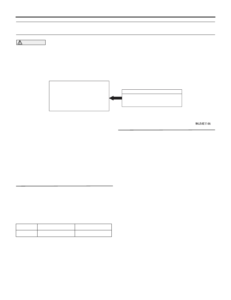
ETACS-ECU
WINDSHIELD WIPER
INTERMITTENT VOLUME
INPUT SIGNAL
Windshield Wiper Intermittent Volume Input Signal
Item No.
Item name
Normal condition
Item 37
INT WIPER TIME
2.4
− 18.0 s

SYMPTOM PROCEDURES
SMART WIRING SYSTEM (SWS) USING SWS MONITOR
54C-162
INSPECTION PROCEDURE F-6: The intermittent wiper interval is not changed according to the
vehicle speed.
CAUTION
Whenever the ECU is replaced, ensure that the
input and output signal circuits are normal.
COMMENTS ON TROUBLE SYMPTOM
The ETACS-ECU calculates the intermittent wiper
interval according to the vehicle speed signal which
is sent by the engine-ECU.
If the intermittent wiper interval does not depend on
the vehicle speed, the input circuit of the vehicle
speed signal and the ETACS-ECU may be defective.
POSSIBLE CAUSES
• Malfunction of the vehicle speed signal
(engine-ECU)
• Malfunction of the ETACS-ECU
• Damaged harness wires and connectors
DIAGNOSIS PROCEDURE
Step 1. Check the adjustment function.
Check that the vehicles speed sensing function has
been enabled by using the adjustment function.
Q: Is the check result normal?
YES :
Go to Step 2.
NO :
Enable the vehicles speed sensing function
by using the adjustment function. (Refer to
).
Step 2. Retest the system.
Check that the windshield intermittent wiper interval
can be adjusted by operating the windshield intermit-
tent wiper volume control.
Q: Is the check result normal?
YES :
Go to Step 3.
NO :
Refer to Inspection Procedure F-5 "The
intermittent wiper interval cannot be
adjusted by operating the windshield
intermittent wiper volume control
."
ETACS-ECU
VEHICLE SPEED
INPUT SIGNAL
Vehicles Speed Input Signal
Нет комментариевНе стесняйтесь поделиться с нами вашим ценным мнением.
Текст