Mitsubishi Lancer Evolution IX. Manual — part 651

SEAT BELTS WITH PRE-TENSIONER
SUPPLEMENTAL RESTRAINT SYSTEM (SRS)
52B-117
SEAT BELTS WITH PRE-TENSIONER
REMOVAL AND INSTALLATION
M1524004100390
WARNING
•
Never attempt to disassemble or repair the seat belt pre-tensioner. If faulty, replace it.
•
Be extremely careful when handling the seat with pre-tensioner. Do not subject it to
shocks, drop it, bring it close to strong magnets or allow contact with water, grease or oil.
Always replace it with a new part if any dents, cracks or deformation is found.
•
Do not place anything on top of the seat belt pre-tensioner.
•
Do not expose the seat belt with pre-tensioner to temperatures over 90
°
C.
•
After operating the seat belt pre-tensioner, replace the seat belt with pre-tensioner with a
new part.
•
Gloves and protective goggles should be worn when handling a seat belt pre-tensioner
once it has been used.
•
If disposing of a seat belt with pre-tensioner which has not yet been operated, its seat belt
pre-tensioner should be operated first before disposal (Refer to
).
Pre-removal Operation
• Turn the ignition switch to the "LOCK" (OFF) position.
• Disconnect the Negative Battery Terminal.
AC101710 AC
1
2
3
4
5
6
44 ± 10 N·m
44 ± 10 N·m

SEAT BELTS WITH PRE-TENSIONER
SUPPLEMENTAL RESTRAINT SYSTEM (SRS)
52B-118
NOTE: The figure shows the seat belt with pre-ten-
sioner (RH).
REMOVAL SERVICE POINTS
<<A>>PRE-TENSIONER CONNECTOR
DISCONNECTION
1. Use a flat-tipped screwdriver to pull out forward
and unlock the locking button of the harness-side
connector.
2. Disconnect the pre-tensioner connector.
INSTALLATION SERVICE POINTS
>>A<< PRE-INSTALLATION INSPECTION
WARNING
When discarding the seat belt with pre-ten-
sioner, operate the pre-tensioner as speci-
fied in the service procedure (Refer to
1. Even new seat belt with pre-tensioner require
inspection before installation.
2. Connect the negative battery cable.
CAUTION
To prevent damage to M.U.T.-II/III, always turn the
ignition, switch to the “LOCK” (OFF) position
before connecting or disconnecting M.U.T.-II/III.
3. Connect M.U.T.-II/III to the diagnosis connector.
Removal steps
1. Sash guide cover
2. Seat belt shoulder anchor bolt
3. Seat belt lower anchor bolt
•
Centre pillar trim, lower (Refer to
GROUP 52A
<<
A
>>
4. Pre-tensioner connector connection
5. Bracket
6. Seat belt with pre-tensioner
Installation steps
>>
A
<< • Pre-installation inspection
6. Seat belt with pre-tensioner
5. Bracket
>>
B
<< 4. Pre-tensioner connector connection
•
Centre pillar trim, lower (Refer to
GROUP 52A
3. Seat belt lower anchor bolt
2. Seat belt shoulder anchor bolt
1. Sash guide cover
•
Negative battery cable connection
>>
C
<< • Post-installation inspection
AC300147 AS
Pre-tensioner
connector
Flat-tipped
screwdriver
Locking button
Harness side connector
AC304777
Steering shaft
AB
MB991502
<Using the M.U.T.-II>
AC211686
MB991911
16-PIN
MB991827
MB991824
AE
<Using the M.U.T.-III>
SEAT BELTS WITH PRE-TENSIONER
SUPPLEMENTAL RESTRAINT SYSTEM (SRS)
52B-119
4. Turn the ignition switch to the ON position.
5. Check diagnosis codes using M.U.T.-II/III to
ensure that the SRS operates properly.
Confirm that the diagnosis codes other than 26
and 28 are not set.
6. Turn the ignition switch to "LOCK" (OFF) position.
DANGER
Wait at least 60 seconds after the disconnec-
tion of the battery cable before any further
job (Refer to
7. Disconnect the negative battery cable and
insulate with tape.
>>B<< PRE-TENSIONER CONNECTOR
CONNECTION
Connect the pretensioner connector then securely
lock the locking button of the harness-side connec-
tor.
>> C<< POST-INSTALLATION
INSPECTION
1. Connect the negative battery cable.
2. Turn the ignition switch to "ON" position.
3. Does the SRS warning lamp illuminate for about 7
seconds and then goes out?
4. If no, refer to troubleshooting (Refer to
).
INSPECTION
M1524004200245
WARNING
•
If any component damage is found during
the following inspection, replace the seat
belt with pre-tensioner with a new one.
Dispose of the old one according to the
specified procedure (Refer to
).
•
Never attempt to measure the circuit
resistance of the seat belt pre-tensioner
even if you are using the specified tester.
If the circuit resistance is measured with a
tester, accidental seat belt pre-tensioner
operation will result in serious personal
injury.
1. Check the seat belt pre-tensioner deployment
section for dents and deformation.
2. Check the harness and connector for damage and
the terminals for deformation.
AC311044
SRS warning lamp
AB
AIR BAG MODULE AND SEAT BELT PRE-TENSIONER DISPOSAL PROCEDURES
SUPPLEMENTAL RESTRAINT SYSTEM (SRS)
52B-120
AIR BAG MODULE AND SEAT BELT PRE-TENSIONER
DISPOSAL PROCEDURES
M1524001200989
Before disposing of an air bag or a vehicle equipped
with an air bag, follow the procedures below to
deploy the air bag.
UNDEPLOYED AIR BAG MODULE DIS-
POSAL
WARNING
•
If the vehicle is to be scrapped or other-
wise disposed of, deploy the air bags and
operate the seat belt pre-tensioner inside
the vehicle. If the vehicle will continue to
be used and only the air bag modules and
seat belt pre-tensioner are to be disposed
of, deploy the air bags and operate the
seat belt pre-tensioner outside the vehi-
cle.
•
Since a large amount of smoke is pro-
duced when the air bag is deployed and
the seat belt pre-tensioner is operated,
avoid residential areas whenever possi-
ble.
•
Since there is loud noise when the air
bags are deployed and when the seat belt
pre-tensioner are operated, avoid residen-
tial areas whenever possible. If anyone is
nearby, give warning of the impending
noise.
•
Suitable ear protection should be worn by
personnel performing these procedures
or by people in the immediate area.
DEPLOYMENT INSIDE THE VEHICLE
(WHEN DISPOSING OF A VEHICLE)
<DRIVER'S AIR BAG MODULE>
1. Move the vehicle to an isolated spot.
DANGER
Wait at least 60 seconds after the disconnec-
tion of the battery cable before any further
job (Refer to
2. Disconnect the negative and positive battery
cables from the battery terminals, and then
remove the battery from the vehicle.
3. Remove the column cover lower (Refer to
GROUP 37
− Steering shaft
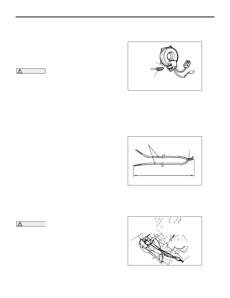
4. Remove the connection between the C-205 clock
spring connector (4-pin) and the harness side
connector (4-pin, yellow).
NOTE: Once disconnected from the instrument
panel wiring harness, both electrodes of the clock
spring connector short automatically. This pre-
vents the driver's air bag from accidental deploy-
ment caused by static, etc.
5. Obtain two suitable wires, which are 6 meters or
longer, as deployment wires. Then connect the
wires at one end to short.
6. Touch the vehicle's body with bare hands to
discharge static in you.
AC300379
C-205 Clock spring
connector (4-pin)
C-205 Harness side
connector
(4-pin, yellow)
AD
AC300381AD
Deployment wires
Connection
6 m or longer
AC300384
Deployment wire
AC
Insulator tape
C-205 Clock spring
connector (4-pin)
Connection
C-205 Harness side
connector
(4-pin, yellow)
Нет комментариевНе стесняйтесь поделиться с нами вашим ценным мнением.
Текст