Mitsubishi Lancer Evolution IX. Manual — part 96
INSTRUMENT PANEL ASSEMBLY
INTERIOR
52A-3
CAUTION
• Refer to GROUP 52B, SRS Service Precautions
and Driver’s, Passenger’s (front) Air Bag
Module and Clock Spring
before removing the passenger’s (front) air bag module.
•
Pre-removal and Post-installation Operation
• Removal and Installation of Front Pillar Trim (Refer to
• Hood Opener Lever (Refer to GROUP 42, Hood
).
AC309832 AC
14
12
11
17
15
16
18
19
21
20
13
3
1
18
8
5
6
7
9
10
4
e
e
e
e
e
e
c
a
a
a
b
c
c
b
a
e
e
e
2
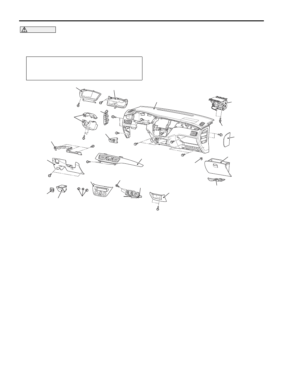
Removal steps
1. Column cover
2. Meter bezel
3. Combination meter
4. Instrument panel ornament
5. Under cover
6. Switch panel
7. Side box
8. Lower frame
9. Heater control knob
10. Centre panel
11. Heater control assembly mounting
screw
12. Heater control assembly
13. Centre air outlet panel
14. Centre lower case
15. Stopper
16. Glove box
17. Harness cover
18. Instrument panel side cover
19. SRS passenger’s (front) air bag
module mounting bolt
•
Steering column shaft mounting bolt
(Refer to GROUP 37, Steering
Column Shaft
).
20. Instrument panel assembly
<<
A
>>
21. SRS passenger’s (front) air bag
module
Do not subject the SRS-ECU to any shocks when removing or installing the instrument panel.
Removal steps (Continued)
INSTRUMENT PANEL ASSEMBLY
INTERIOR
52A-4
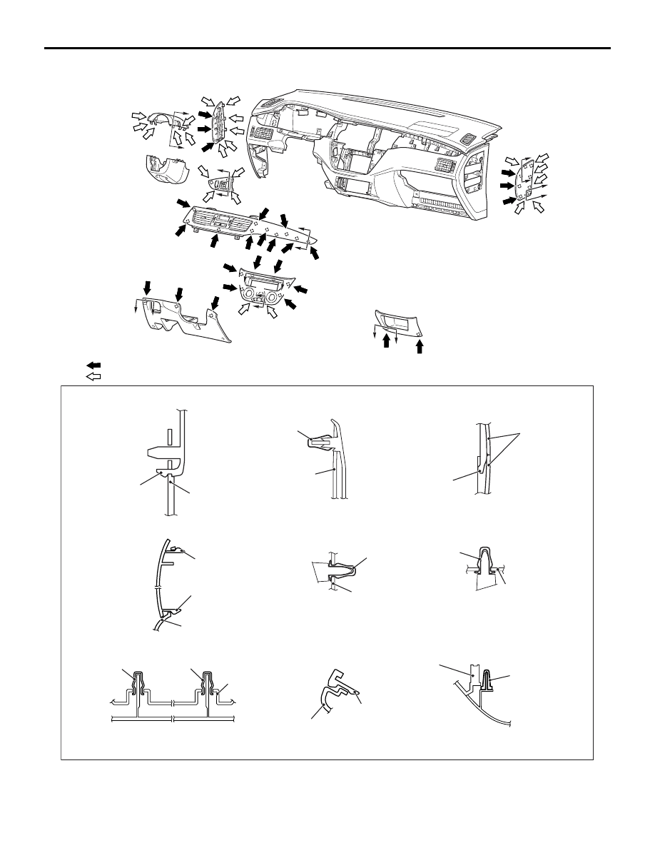
CLIP AND CLAW POSITION
AC504401 AB
A
A
B
B
I
I
F
F
H
H
G
G
E
E
D
D
C
C
Note
(1) : Clip positions
(2) : Claw positions
Section A – A
Section B – B
Section C – C
Section F – F
Section E – E
Section D – D
Section G – G
Section H – H
Section I – I
Claw
Instrument panel
assembly
Clip
Instrument panel
assembly
Column cover
Claw
Instrument panel
assembly
Clip
Instrument panel
assembly
Clip
Instrument panel
assembly
Clip
Claw
Instrument panel
assembly
Instrument panel
assembly
Clip
Claw
Claw
Instrument panel
assembly
Clip
INSTRUMENT PANEL ASSEMBLY
INTERIOR
52A-5
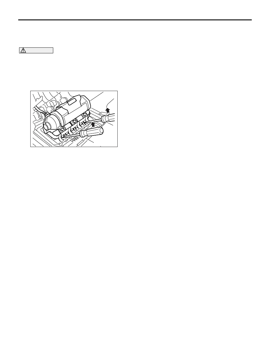
REMOVAL SERVICE POINT
<<A>> SRS PASSENGER’S (FRONT) AIR
BAG MODULE REMOVAL
CAUTION
• Do not damage the claws of the hinge when
removing the passenger’s (front) air bag mod-
ule.
•
AC005174
Store the removed passenger’s (front) air bag
module with the deployed side facing upward,
in a clean and dry place.
Insert the flat-tipped screwdriver into the position
shown in the illustration and pull up the screwdriver
to disengage the claws for removal of the passen-
ger’s (front) air bag module.
INSTRUMENT PANEL ASSEMBLY
INTERIOR
52A-6
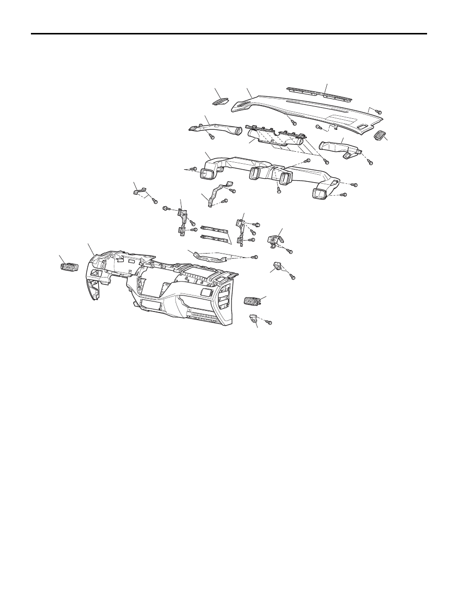
DISASSEMBLY AND REASSEMBLY
M1521001900622
AC005175
15
16
11
15
1
9
8
10
7
6
7
5
4
2
13
3
12
2
14
13
d
d
d
d
d
d
d
d
d
d
d
d
d
f
d
d
d
d
d
d
d
f
d
d
AG
Disassembly steps
1. Instrument panel upper support
2. Side defroster duct
3. Centre defroster duct
4. Distribution duct
5. Driver side upper bracket
6. Centre upper reinforcement
7. Instrument panel centre
reinforcement
8. Bridge reinforcement
9. Centre lower reinforcement
10. Glove box striker
11. Glove box cover
12. Instrument panel pad
13. Side demister
14. Defroster garnish
15. Side air outlet assembly
16. Instrument panel
Disassembly steps (Continued)
Нет комментариевНе стесняйтесь поделиться с нами вашим ценным мнением.
Текст