Mitsubishi Lancer Evolution IX. Manual — part 500

TROUBLESHOOTING
ANTI-SKID BRAKING SYSTEM (ABS)
35B-31
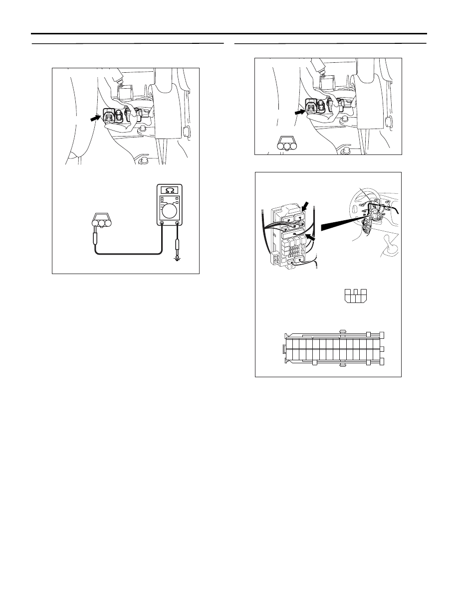
STEP 3. Check the following harness wires.
•
The wire between fusible link No.3 and ABS-ECU
connector B-118 (terminal 11)
• The wire between fusible link No.3 and ABS-ECU
connector B-118 (terminal 33)
Q: Is any harness wire damaged?
YES :
Repair or replace it and then go to Step 4.
NO :
Go to Step 4.
STEP 4. Check whether the diagnosis code is
reset.
Check again if the diagnosis code is set.
(1) Turn the ignition switch to the "ON" position.
(2) Erase the diagnosis code.
(3) Turn the ignition switch to the "LOCK" (OFF)
position.
(4) Turn the ignition switch to the "ON" position.
(5) Check if the diagnosis code is set.
(6) Turn the ignition switch to the "LOCK" (OFF)
position.
Q: Do diagnosis codes 41, 42, 43, 44, 52, 53 or 55
reset?
YES :
Return to Step 1.
NO :
The procedure is complete.
AC208825 AL
Fusible link: No.3
No.3
AC211901AD
B-118 (B)
Connector: B-118
28
32
34
12
11
33
30
21
9
10
22
31
7
8
29
20 19
24
2
26
4
5
6
27
18 17
3
25
16 15
1
23
13
14
Harness side
AC207179AB
M.U.T.-II
16-PIN
<Using the M.U.T.-II>
AC210056
AC
MB991911
16-PIN
MB991827
MB991824
<Using the M.U.T.-III>

TROUBLESHOOTING
ANTI-SKID BRAKING SYSTEM (ABS)
35B-32
Code No.71: Lateral G-Sensor System
OPERATION
The lateral G-sensor detects the acceleration level in
the left/right direction of the vehicle, converts the sig-
nals into voltage signals and then sends that signal
to the ABS-ECU.
DIAGNOSIS CODE SET CONDITIONS
This code is set in the following cases:
• When the G-sensor output is 0.5 V or lower or
4.5 V or higher (disconnected lateral G-sensor or
lateral G-sensor short circuit)
• If the lateral G-sensor output power does not
change (lateral G-sensor output fastening).
PROBABLE CAUSES
The most likely causes for diagnosis code to set are:
• Malfunction of the lateral G-sensor
• Damaged wiring harness and connector
• Malfunction of the brake modulator hydraulic unit
(integrated with ABS-ECU)
IGNITION
SWITCH (IG2)
G-SENSOR
(LATERAL)
ABS-ECU
Wire colour code
B : Black LG : Light green G : Green L : Blue W : White Y : Yellow SB : Sky blue
BR : Brown O : Orange GR : Gray R : Red P : Pink V : Violet
Lateral G-Sensor Circuit

TROUBLESHOOTING
ANTI-SKID BRAKING SYSTEM (ABS)
35B-33
DIAGNOSIS
STEP 1.M.U.T.-II/III data list.
CAUTION
To prevent damage to M.U.T.-II/III, always turn the
ignition switch to the "LOOK" (OFF) position
before connecting or disconnecting M.U.T.-II/III.
(1) Connect M.U.T.-II/III as shown in the illustration.
(2) Start the engine.
(3) Set M.U.T.-II/III to data reading mode for following
item.
• Item 71: Lateral G-sensor
OK:
When vehicle is stationary (level): 2.4
− 2.6
V
When vehicle is being driven: 1.0
− 4.0 V
Q: Is the lateral G-sensor input normal?
YES :
This malfunction is intermittent. Refer to
GROUP 00, How to Use
Troubleshooting/Inspection Service Points
−
How to Cope With Intermittent Malfunction
.
NO :
Go to Step 2.
STEP 2. Check the power supply circuit. Voltage
measurement at lateral G-sensor connector D-37.
(1) Disconnect connector D-37, and check at the
harness side.
(2) Turn the ignition switch to the "ON" position.
(3) Measure the voltage between terminal 1 and
earth.
OK: System voltage
Q: Is the check result normal?
YES :
Go to Step 3.
NO :
Go to Step 4.
AC207179AB
M.U.T.-II
16-PIN
<Using the M.U.T.-II>
AC210056
AC
MB991911
16-PIN
MB991827
MB991824
<Using the M.U.T.-III>
AC212253AD
Connector: D-37
D-37 (B)
Connector D-37
(Harness side)
3
1
2
TROUBLESHOOTING
ANTI-SKID BRAKING SYSTEM (ABS)
35B-34
STEP 3. Check the earth circuit. Resistance
measurement at lateral G-sensor connector D-37.
(1) Disconnect connector D-37, and check at the
harness side.
(2) Measure the resistance between terminal 3 and
earth.
OK: 2 ohms or less
Q: Is the resistance 2 ohms or less?
YES :
Go to Step 8.
NO :
Go to Step 6.
STEP 4. Check the following connectors.
•
Lateral G-sensor connector D-37
•
Junction block connectors C-211, C-214
Check the connectors for loose, corroded or dam-
aged terminals, or terminals pushed back in the con-
nector.
Q: Are the connectors and terminals in good
condition?
YES :
Go to Step 5.
NO :
Repair it and then go to Step 11.
AC212253
AD
Connector: D-37
D-37 (B)
Connector D-37
(Harness side)
3
1
2
AE
AC208854AF
Connector: D-37
D-37 (B)
Harness side
3
1
2
AC212152AD
Connectors: C-211, C-214
C-211
C-214
Junction block
(Front view)
Connector C-211
(Harness side)
Connector C-214
(Harness side)
4
6 5
3
2
1
21
7
16 15
17
18
20 19
1
2
3
4
5
6
23 22
24
25
28
26
27
9
8
10
11
14
12
13
Нет комментариевНе стесняйтесь поделиться с нами вашим ценным мнением.
Текст