Mitsubishi Lancer Evolution IX. Manual — part 498

TROUBLESHOOTING
ANTI-SKID BRAKING SYSTEM (ABS)
35B-23
DIAGNOSIS
STEP 1.M.U.T.-II/III data list.
CAUTION
To prevent damage to M.U.T.-II/III, always turn the
ignition switch to the "LOOK" (OFF) position
before connecting or disconnecting M.U.T.-II/III.
(1) Connect M.U.T.-II/III as shown in the illustration.
(2) Start the engine.
(3) Set M.U.T.-II/III to data reading mode for following
item.
• Item 32: Longitudinal G-sensor
OK:
When vehicle is stationary (level): 2.4
−
2.6 V
When vehicle is being driven: 1.0
− 4.0 V
Q: Is the longitudinal G-sensor input normal?
YES :
This malfunction is intermittent. Refer to
GROUP 00, How to Use
Troubleshooting/Inspection Service Points
−
How to Cope With Intermittent Malfunction
.
NO :
Go to Step 2.
STEP 2. Check the power supply circuit. Voltage
measurement at longitudinal G-sensor connector
D-38.
(1) Disconnect connector D-38, and check at the
harness side.
(2) Turn the ignition switch to the "ON" position.
(3) Measure the voltage between terminal 1 and
earth.
OK: System voltage
Q: Is the check result normal?
YES :
Go to Step 3.
NO :
Go to Step 4.
AC207179AB
M.U.T.-II
16-PIN
<Using the M.U.T.-II>
AC210056
AC
MB991911
16-PIN
MB991827
MB991824
<Using the M.U.T.-III>
AC212253AB
Connector: D-38
D-38 (B)
Connector D-38
(Harness side)
3
1
2

TROUBLESHOOTING
ANTI-SKID BRAKING SYSTEM (ABS)
35B-24
STEP 3. Check the earth circuit. Resistance
measurement at longitudinal G-sensor
connector D-38.
(1) Disconnect connector D-38, and check at the
harness side.
(2) Measure the resistance between terminal 3 and
earth.
OK: 2 ohms or less
Q: Is the resistance 2 ohms or less.
YES :
Go to Step 8.
NO :
Go to Step 6.
STEP 4. Check the following connectors.
•
Longitudinal G-sensor connector D-38
•
Junction block connectors C-211, C-214
Check the connectors for loose, corroded or dam-
aged terminals, or terminals pushed back in the con-
nector.
Q: Are the connectors and terminals in good
condition?
YES :
Go to Step 5.
NO :
Repair it and then go to Step 11.
AC212253
AD
Connector: D-38
D-38 (B)
Connector D-38
(Harness side)
3
1
2
AC
AC208854AE
Connector: D-38
D-38 (B)
Harness side
3
1
2
AC212152AD
Connectors: C-211, C-214
C-211
C-214
Junction block
(Front view)
Connector C-211
(Harness side)
Connector C-214
(Harness side)
4
6 5
3
2
1
21
7
16 15
17
18
20 19
1
2
3
4
5
6
23 22
24
25
28
26
27
9
8
10
11
14
12
13

TROUBLESHOOTING
ANTI-SKID BRAKING SYSTEM (ABS)
35B-25
STEP 5. Check the following harness wire.
•
The wire between longitudinal G-sensor connector
D-38 (terminal 1) and junction block connector
C-211 (terminal 2)
Q: Is the harness wire damaged?
YES :
Repair or replace it and then go to Step 11.
NO :
Go to Step 11.
STEP 6. Check the following connectors.
•
Longitudinal G-sensor connector D-38
•
Intermediate connector C-124
•
ABS-ECU connector B-118
Check the connectors for loose, corroded or dam-
aged terminals, or terminals pushed back in the con-
nector.
Q: Are the connectors and terminals in good
condition?
YES :
Go to Step 7.
NO :
Repair it and then go to Step 11.
AC208854AE
Connector: D-38
D-38 (B)
Harness side
3
1
2
AC211269
Connector: C-211
AL
Junction block
(Front view)
Harness side
4
6 5
3
2
1
AC208854AE
Connector: D-38
D-38 (B)
Harness side
3
1
2
AC211265
Connector: C-124
AR
18
3
16
15
14
1 2
17
4 5
8
20
19
6 7
2122
9 10
25
13
24
23
12
11
AC211901AD
B-118 (B)
Connector: B-118
28
32
34
12
11
33
30
21
9
10
22
31
7
8
29
20 19
24
2
26
4
5
6
27
18 17
3
25
16 15
1
23
13
14
Harness side
TROUBLESHOOTING
ANTI-SKID BRAKING SYSTEM (ABS)
35B-26
STEP 7. Check the following harness wire.
•
The wire between longitudinal G-sensor connector
D-38 (terminal 3) and ABS-ECU connector B-118
(terminal 15)
Q: Is the harness wire damaged?
YES :
Repair or replace it and then go to Step 11.
NO :
Go to Step 11.
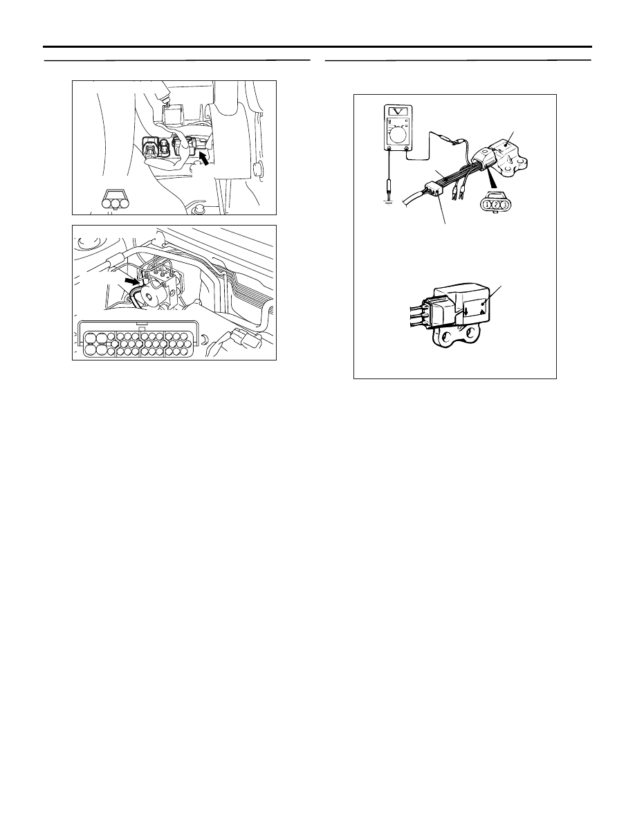
STEP 8. Check longitudinal G-sensor output
voltage.
(1) Disconnect connector D-38, and then connect
special tool harness set (MB991348) between
terminals of the disconnected connectors.
(2) Turn the ignition switch to the "ON" position.
(3) Measure the voltage between terminal 2 and
earth.
OK:
When the longitudinal G-sensor is placed
on a level plane: 2.4
− 2.6 volts
When the longitudinal G-sensor is placed
with its label positioned as shown: 3.4
−
3.6 volts
Q: Is the longitudinal G-sensor output voltage
normal?
YES :
Go to Step 9.
NO :
Replace the longitudinal G-sensor (Refer to
). Then go to Step 11.
AC208854AE
Connector: D-38
D-38 (B)
Harness side
3
1
2
AC211901AD
B-118 (B)
Connector: B-118
28
32
34
12
11
33
30
21
9
10
22
31
7
8
29
20 19
24
2
26
4
5
6
27
18 17
3
25
16 15
1
23
13
14
Harness side
AC103662AG
MB991348
Connector: D-38
(Harness side)
Label
Label
Нет комментариевНе стесняйтесь поделиться с нами вашим ценным мнением.
Текст