Mitsubishi Lancer Evolution IX. Manual — part 470

TROUBLESHOOTING
MULTIPORT FUEL INJECTION (MPI)
13A-355
STEP 7. Check harness between C-37 (terminal
No. 32) A/C-ECU connector and C-119 (terminal
No. 65) engine-ECU connector.
NOTE: Before checking harness, check intermediate
connector C-124
*1
or C-122
*2
, and repair if neces-
sary.
• Check output line for short circuit.
Q: Is the check result normal?
YES :
Check Air conditioner (Refer to GROUP 55
− Troubleshooting − Check Chart For
Trouble Symptoms
NO :
Repair the damaged harness wire.
STEP 8. Connector check: C-37 A/C-ECU
connector
Q: Is the check result normal?
YES :
Check intermediate connector C-124
*1
or
C-122
*2
, and repair if necessary. If
intermediate connector is normal, check and
repair harness between C-37 (terminal No.
32) A/C-ECU connector and C-119 (terminal
No. 65) engine-ECU connector.
• Check output line for open circuit.
NO :
Repair or replace the connector.
AK502007
28
36
27
35
26
34
25
33
24
32
23
31
22
30
21
29
AB
C-37 (B)
Harness side
connector
Connector: C-37
AK501994
65
43
50
42
49
41
48
60
61
64
46
47
58
59
67
68
45
56
66
52 51
44
53
62
54
63
57
55
AB
Connector: C-119
C-119 (GR)
C-119 (GR)
Harness side connector
<L. H. drive vehicles>
<R. H. drive vehicles>

TROUBLESHOOTING
MULTIPORT FUEL INJECTION (MPI)
13A-356
Inspection Procedure 30: Ignition Circuit System <L. H. drive vehicles>
1 2 3
1 2 3
AK501836
1 2 3
4 5 6
2
3 4
5 6
7 8
9
11 12 13 14 15 16 17 18 19 20
30
21 22 23
24 25
26 27 28 29
3132 33
34 35
1
10
LOCK
ACC
IG1
R
IG2
ST
10 A
Engine-ECU
2
1
1
3
3
2
11
12
Ignition switch
C-208
B-W
Y-G
W
W-R
W-R
B-Y
B
B
B
B
B-G
2
10
C-214
C-129
18
4
A-29
6
C-211
J/B
Ignition circuit
Spark
plug
AB
Ignition coil 2
B-114
(MU802064)
Ignition coil 1
B-103
(MU802064)
C-121
(MU803784)
1
Wire colour code
B: Black LG: Light green G: Green L: Blue W: White Y: Yellow SB: Sky blue BR: Brown O: Orange GR: Gray
R: Red P: Pink V: Violet PU: Purple
TROUBLESHOOTING
MULTIPORT FUEL INJECTION (MPI)
13A-357
OPERATION
• The battery voltage is applied to the ignition coil
(terminal No. 1) from the ignition switch and is
earthed to the vehicle body from the ignition coil
(terminal No. 2).
• A power voltage of 12 V is applied to the ignition
coil output terminal (terminal No. 3) from the
engine-ECU (terminal No. 11 and No. 12).
FUNCTION
• When the engine-ECU makes the power transis-
tor in the unit be in "OFF" position, the battery
voltage in the unit is applied to the power transis-
tor unit, and that makes the power transistor unit
be in "ON" position. The engine-ECU makes the
power transistor in the unit be in "ON", and that
makes the power transistor unit be in "OFF" posi-
tion.
• In response to the signal from the engine-ECU,
the power transistor unit is in "ON" position. The
primary current is going to the ignition coil. When
the power transistor unit is in "OFF" position, the
primary current is interrupted and high voltage is
generated in the secondary coil.
PROBABLE CAUSES
• Failed ignition coil
• Failed spark plug
• Failed spark plug cable
• Open/short circuit in ignition primary circuit or
loose connector contact
• Failed engine-ECU
DIAGNOSIS PROCEDURE
STEP 1. Check spark plug cable itself.
• Check spark plug cable itself (Refer to GROUP
16
− Ignition System − On-vehicle Service
Q: Is the check result normal?
YES :
Go to Step 2 .
NO :
Replace the spark plug cable.
STEP 2. Check spark plug.
Q: Is the check result normal?
YES :
Go to Step 3 .
NO :
Replace the spark plug.
STEP 3. Connector check: B-103 and B-114
ignition coil connectors
Q: Is the check result normal?
YES :
Go to Step 4 .
NO :
Repair or replace the connector.
STEP 4. Check ignition coil itself.
• Check ignition coil itself (Refer to GROUP 16 −
Ignition System
Q: Is the check result normal?
YES :
Go to Step 5 .
NO :
Replace the ignition coil.
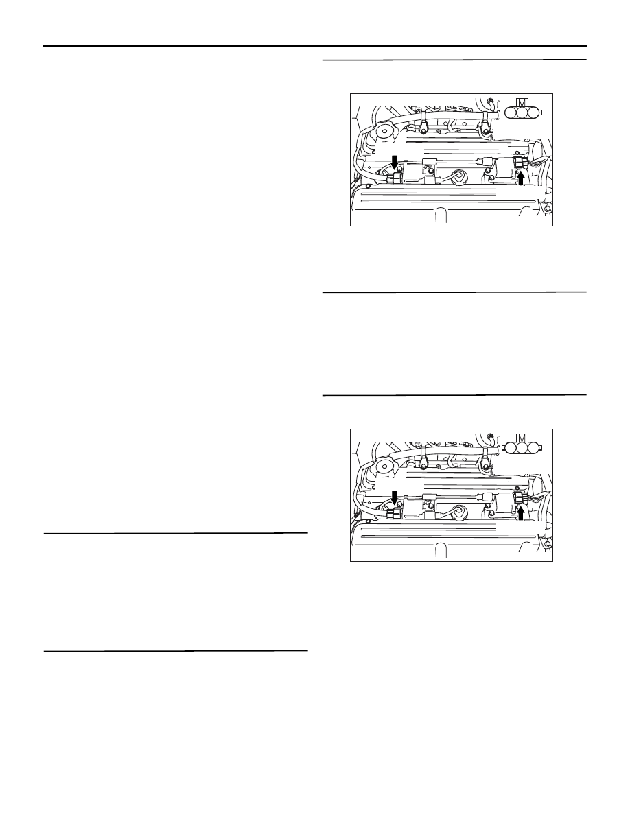
STEP 5. Perform voltage measurement at B-103
and B-114 ignition coil connectors.
• Disconnect connector, and measure at harness
side.
• Ignition switch: "ON"
• Voltage between terminal No. 1 and earth.
OK: System voltage
Q: Is the check result normal?
YES :
Go to Step 7 .
NO :
Go to Step 6 .
AK305047
1
2
3
Connector : B-103, B-114
B-114(GR)
B-103(GR)
AB
Harness side
connector
AK305047
1
2
3
Connector : B-103, B-114
B-114(GR)
B-103(GR)
AB
Harness side
connector
TROUBLESHOOTING
MULTIPORT FUEL INJECTION (MPI)
13A-358
STEP 6. Connector check: C-208 ignition switch
connector
Q: Is the check result normal?
YES :
Check intermediate connectors A-29,
C-129, C-211 and C-214, and repair if
necessary. If intermediate connectors are
normal, check and repair harness between
C-208 (terminal No. 2) ignition switch
connector and B-114 (terminal No. 1)
ignition coil connector, also between C-208
(terminal No. 2) ignition switch connector
and B-103 (terminal No. 1) ignition coil
connector.
• Check power supply line for
open/short circuit.
NO :
Repair or replace the connector.
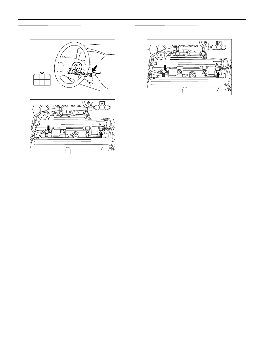
STEP 7. Perform voltage measurement at B-103
and B-114 ignition coil connectors.
• Disconnect connector, and measure at harness
side.
• Engine: Cranking
• Voltage between terminal No. 3 and earth.
OK: 0.5
− 4.0 V
Q: Is the check result normal?
YES :
Go to Step 13 .
NO :
Go to Step 8 .
1
2
3
4
5
6
AK305446
Harness side
connector
Connector: C-208
C-208
AB
AK305047
1
2
3
Connector : B-103, B-114
B-114(GR)
B-103(GR)
AB
Harness side
connector
AK305047
1
2
3
Connector : B-103, B-114
B-114(GR)
B-103(GR)
AB
Harness side
connector
Нет комментариевНе стесняйтесь поделиться с нами вашим ценным мнением.
Текст