Mitsubishi Lancer Evolution IX. Manual — part 471

TROUBLESHOOTING
MULTIPORT FUEL INJECTION (MPI)
13A-359
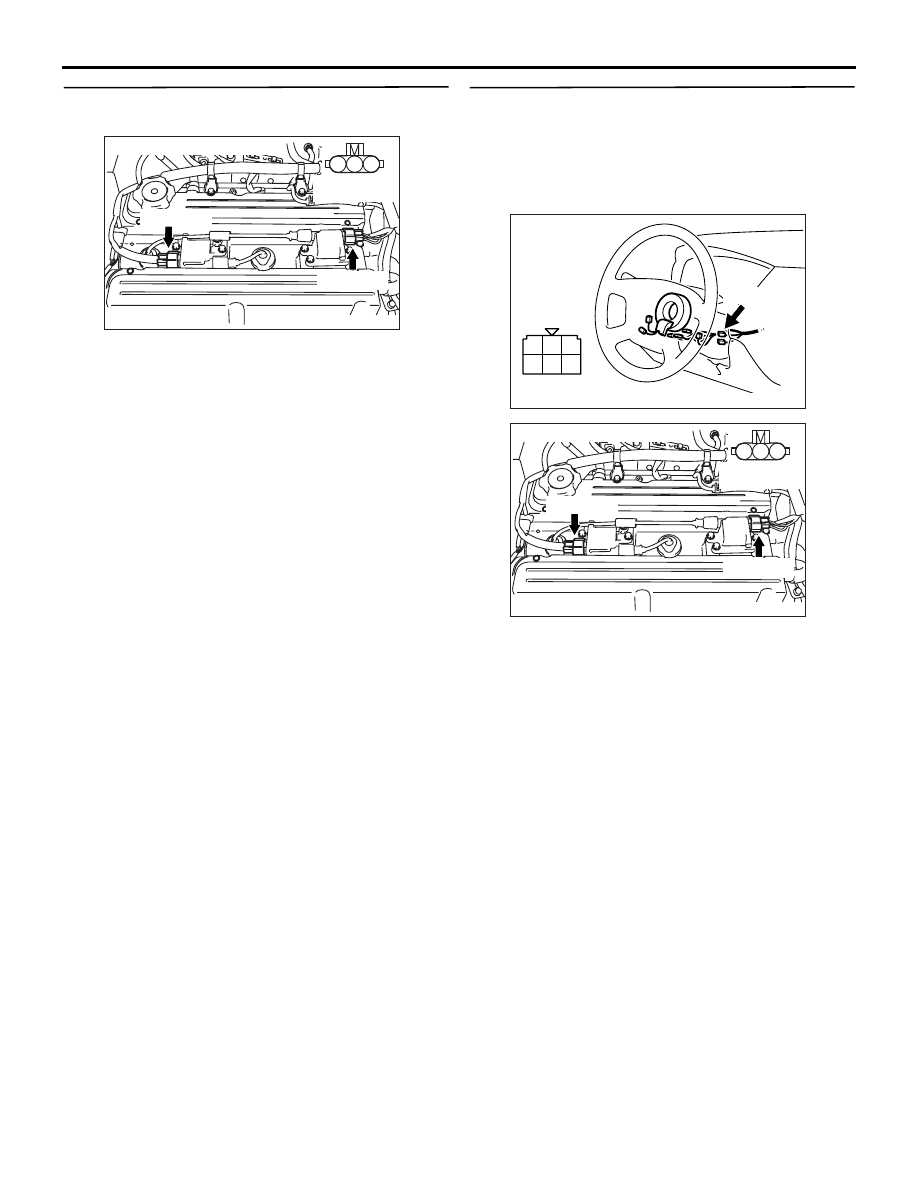
STEP 8. Perform voltage measurement at C-121
engine-ECU connector.
• Measure engine-ECU terminal voltage.
• Disconnect B-103 and B-114 ignition coil connec-
tors.
• Engine: Cranking
• Voltage between terminal No. 11 and earth, also
between terminal No. 12 and earth.
OK: 0.5
− 4.0 V
Q: Is the check result normal?
YES :
Go to Step 9 .
NO :
Go to Step 10 .
STEP 9. Connector check: C-121 engine-ECU
connector
Q: Is the check result normal?
YES :
Check and repair harness between B-114
(terminal No. 3) ignition coil connector and
C-121 (terminal No. 12) engine-ECU
connector, also between B-103 (terminal
No. 3) ignition coil connector and C-121
(terminal No. 11) engine-ECU connector.
• Check output line for open circuit.
NO :
Repair or replace the connector.
AK502032
2
3
4
5
6
7
8
9
11
12
13
14
15
16
17
18
19
20
30
21
22
23
24
25
26
27
28
29
31
32
33
34
35
1
10
AB
Connector: C-121
C-121 (GR)
Harness side connector
AK305047
1
2
3
Connector : B-103, B-114
B-114(GR)
B-103(GR)
AB
Harness side
connector
AK502032
2
3
4
5
6
7
8
9
11
12
13
14
15
16
17
18
19
20
30
21
22
23
24
25
26
27
28
29
31
32
33
34
35
1
10
AB
Connector: C-121
C-121 (GR)
Harness side connector
AK305047
1
2
3
Connector : B-103, B-114
B-114(GR)
B-103(GR)
AB
Harness side
connector

TROUBLESHOOTING
MULTIPORT FUEL INJECTION (MPI)
13A-360
STEP 10. Connector check: C-121 engine-ECU
connector
Q: Is the check result normal?
YES :
Go to Step 11 .
NO :
Repair or replace the connector.
STEP 11. Check harness between B-114 (terminal
No. 3) ignition coil connector and C-121 (terminal
No. 12) engine-ECU connector, also between
B-103 (terminal No. 3) ignition coil connector and
C-121 (terminal No. 11) engine-ECU connector.
• Check output line for short circuit.
Q: Is the check result normal?
YES :
Go to Step 12 .
NO :
Repair the damaged harness wire.
STEP 12. Check the trouble symptoms.
Q: Does trouble symptom persist?
YES :
Replace the engine-ECU.
NO :
Intermittent malfunction (Refer to GROUP
00
− How to Use
Troubleshooting/Inspection Service Points
).
AK502032
2
3
4
5
6
7
8
9
11
12
13
14
15
16
17
18
19
20
30
21
22
23
24
25
26
27
28
29
31
32
33
34
35
1
10
AB
Connector: C-121
C-121 (GR)
Harness side connector
AK305047
1
2
3
Connector : B-103, B-114
B-114(GR)
B-103(GR)
AB
Harness side
connector
AK502032
2
3
4
5
6
7
8
9
11
12
13
14
15
16
17
18
19
20
30
21
22
23
24
25
26
27
28
29
31
32
33
34
35
1
10
AB
Connector: C-121
C-121 (GR)
Harness side connector
TROUBLESHOOTING
MULTIPORT FUEL INJECTION (MPI)
13A-361
STEP 13. Perform resistance measurement at
B-103 and B-114 ignition coil connectors.
• Disconnect connector, and measure at harness
side.
• Resistance between terminal No. 2 and earth.
OK: 2
Ω or less
Q: Is the check result normal?
YES :
Go to Step 14 .
NO :
Check and repair harness between B-103
(terminal No. 2) ignition coil connector and
body earth, also between B-114 (terminal
No. 2) ignition coil connector and body
earth.
• Check earthing line for open circuit
and damage.
STEP 14. Check harness between C-208 (terminal
No. 2) ignition switch connector and B-103
(terminal No. 1) ignition coil connector, also
between C-208 (terminal No. 2) ignition switch
connector and B-114 (terminal No. 1) ignition coil
connector.
NOTE: Before checking harness, check intermediate
connectors A-29, C-129, C-211 and C-214, and
repair if necessary.
• Check power supply line for damage.
Q: Is the check result normal?
YES :
Go to Step 15 .
NO :
Repair the damaged harness wire.
AK305047
1
2
3
Connector : B-103, B-114
B-114(GR)
B-103(GR)
AB
Harness side
connector
1
2
3
4
5
6
AK305446
Harness side
connector
Connector: C-208
C-208
AB
AK305047
1
2
3
Connector : B-103, B-114
B-114(GR)
B-103(GR)
AB
Harness side
connector

TROUBLESHOOTING
MULTIPORT FUEL INJECTION (MPI)
13A-362
STEP 15. Check harness between B-114 (terminal
No. 3) ignition coil connector and C-121 (terminal
No. 12) engine-ECU connector, also between
B-103 (terminal No. 3) ignition coil connector and
C-121 (terminal No. 11) engine-ECU connector.
• Check output line for damage.
Q: Is the check result normal?
YES :
Go to Step 12 .
NO :
Repair the damaged harness wire.
AK305047
1
2
3
Connector : B-103, B-114
B-114(GR)
B-103(GR)
AB
Harness side
connector
AK502032
2
3
4
5
6
7
8
9
11
12
13
14
15
16
17
18
19
20
30
21
22
23
24
25
26
27
28
29
31
32
33
34
35
1
10
AB
Connector: C-121
C-121 (GR)
Harness side connector
Нет комментариевНе стесняйтесь поделиться с нами вашим ценным мнением.
Текст