Mitsubishi Lancer Evolution IX. Manual — part 513

TROUBLESHOOTING
ANTI-SKID BRAKING SYSTEM (ABS)
35B-83
INSPECTION PROCEDURE FOR
TROUBLE SYMPTOMS <L.H. drive
vehicle>
INSPECTION PROCEDURE 1: Communication between the M.U.T.-II/III and all the Systems is Not
Possible.
OPERATION
A battery positive voltage is applied on the diagnosis
connector power terminal (terminal 16). The earth
terminals (terminal 4, 5) are earthed to the vehicle
body.
COMMENT ON TROUBLE SYMPTOM
The cause is probably a defect in power supply cir-
cuit or the earth circuit.
PROBABLE CAUSES
The most likely causes for this case are:
• Malfunction of the diagnosis connector
• Damaged wiring harness or connector
FUSIBLE
LINK
1
DIAGNOSIS
CONNECTOR
FRONT SIDE
Wire colour code
B : Black LG : Light green G : Green L : Blue W : White Y : Yellow SB : Sky blue
BR : Brown O : Orange GR : Gray R : Red P : Pink V : Violet
Diagnosis Connector Power Supply and Earth Circuit

TROUBLESHOOTING
ANTI-SKID BRAKING SYSTEM (ABS)
35B-84
DIAGNOSIS
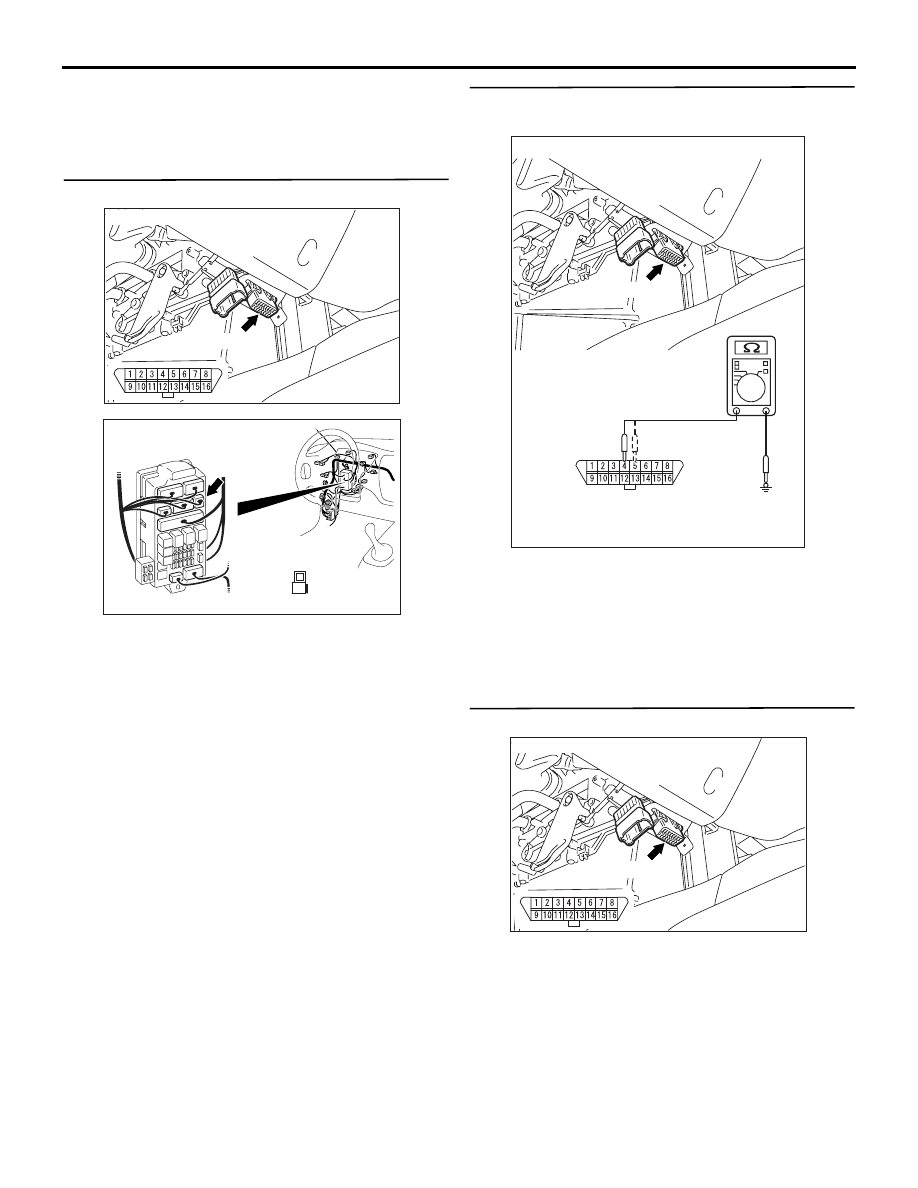
STEP 1. Check the power supply circuit. Voltage
measurement at diagnosis connector C-14.
Measure the voltage between terminal 16 and earth.
OK: System voltage
Q: Is the check result normal?
YES :
Go to Step 4.
NO :
Go to Step 2.
STEP 2. Check the following connectors.
•
Diagnosis connector C-14
•
Junction block connectors C-212, C-214
•
Intermediate connector C-126
Check the connectors for loose, corroded or dam-
aged terminals, or terminals pushed back in the con-
nector.
AC212151AB
Diagnosis connector
C-14(B)
Connector: C-14
AC100188AG
C-14(B)
Connector: C-14
AC212152 AB
Connectors: C-212, C-214
C-212 (B)
C-214
Connector C-212
(harness side)
21
7
16 15
17
18
20 19
1
2
3
4
5
6
23 22
24
25
28
26
27
9
8
10
11
14
12
13
1
Connector C-214
(harness side)
AC211265DG
Connector: C-126
C-126
1
2
3
Harness side
TROUBLESHOOTING
ANTI-SKID BRAKING SYSTEM (ABS)
35B-85
Q: Are the connectors and terminals in good
condition?
YES :
Go to Step 3.
NO :
Repair it and then go to Step 7.
STEP 3. Check the following harness wire.
The wire between diagnosis connector C-14 (termi-
nal 16) and junction block connector C-212 (terminal
1)
Q: Is the harness wire damaged?
YES :
Repair or replace it and then go to Step 7.
NO :
Go to Step 7.
STEP 4. Check the earth circuit. Resistance
measuremen at diagnosis connector C-14.
Measure the resistance between terminal 4 and
earth, and terminal 5 and earth.
OK: 2 ohms or less
Q: Is the resistance 2 ohms or less?
YES :
Replace the M.U.T.-II and then go to Step 7.
NO :
Go to Step 5.
STEP 5. Check the following connector.
•
Diagnosis connector C-14
Check the connector, for loose, corroded or dam-
aged terminals, or terminals pushed back in the con-
nector.
Q: Are the connector and terminals in good
condition?
YES :
Go to Step 6.
NO :
Repair it and then go to Step 7.
AC100188AG
C-14(B)
Connector: C-14
AC211269
Connector: C-212
C-212 (B)
BR
Harness side
1
AC212151AC
Diagnosis connector
C-14(B)
Connector: C-14
AC100188AG
C-14(B)
Connector: C-14

TROUBLESHOOTING
ANTI-SKID BRAKING SYSTEM (ABS)
35B-86
STEP 6. Check the following harness wires.
•
The wire between diagnosis connector C-14 (termi-
nal 4) and earth (No.7)
• The wire between diagnosis connector C-14 (ter-
minal 5) and earth (No.7)
Q: Is any harness wire damaged?
YES :
Repair or replace it and then go to Step 7.
NO :
Go to Step 7.
STEP 7. Retest the system.
Q: Does the M.U.T.-II/III communicate with the whole
system?
YES :
The procedure is complete.
NO :
Return to Step 1.
AC100188AG
C-14(B)
Connector: C-14
AC211897AC
Earth
No.7
Нет комментариевНе стесняйтесь поделиться с нами вашим ценным мнением.
Текст