Mitsubishi Lancer Evolution IX. Manual — part 284

COLUMN SWITCH
CHASSIS ELECTRICAL
54A-73
COLUMN SWITCH
SPECIAL TOOL
M1542000600946
Tool
Number
Name
Use
MB990784
MB990784
Ornament remover Removal of column cover
COLUMN SWITCH
REMOVAL AND INSTALLATION
M1543009100510
AC211607
3
2
4
1
AC
A
A
A
A
A
Section A - A
2
1
Claw
A
A
A
Removal steps
1. Lower column cover
2. Upper column cover
3. Turn-signal and lighting switch
4. Windshield wiper and washer switch
Removal steps (Continued)
COLUMN SWITCH
CHASSIS ELECTRICAL
54A-74
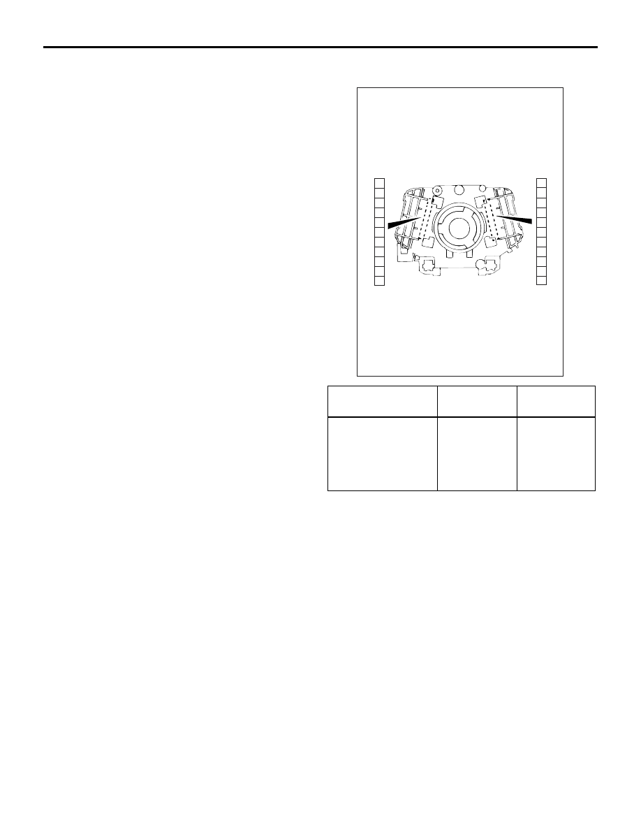
INSPECTION
M1542011201804
COLUMN SWITCH (SWITCH BODY) CON-
TINUITY CHECK
1. Removal the lighting switch and the wiper and
washer switch.
2. Check that there is continuity between the same
terminals [terminals (3) and (11)] of each
connector of the column switch body which is still
on the steering column.
1
6
8
11
10
9
7
5
4
3
2
1
6
8
11
10
9
7
5
4
3
2
AC005499
At lighting
switch side
At wiper/washer
switch side
AD
Column switch
body
Tester
connection
Specified
condition
Lighting switch side
connector, Wiper
and washer switch
side connector
3
− 3, 4 − 4, 5
− 5, 6 − 6, 7 −
7, 8
− 8, 9 − 9,
10
− 10, 11 −
11
Less than 2
ohms
HORN
CHASSIS ELECTRICAL
54A-75
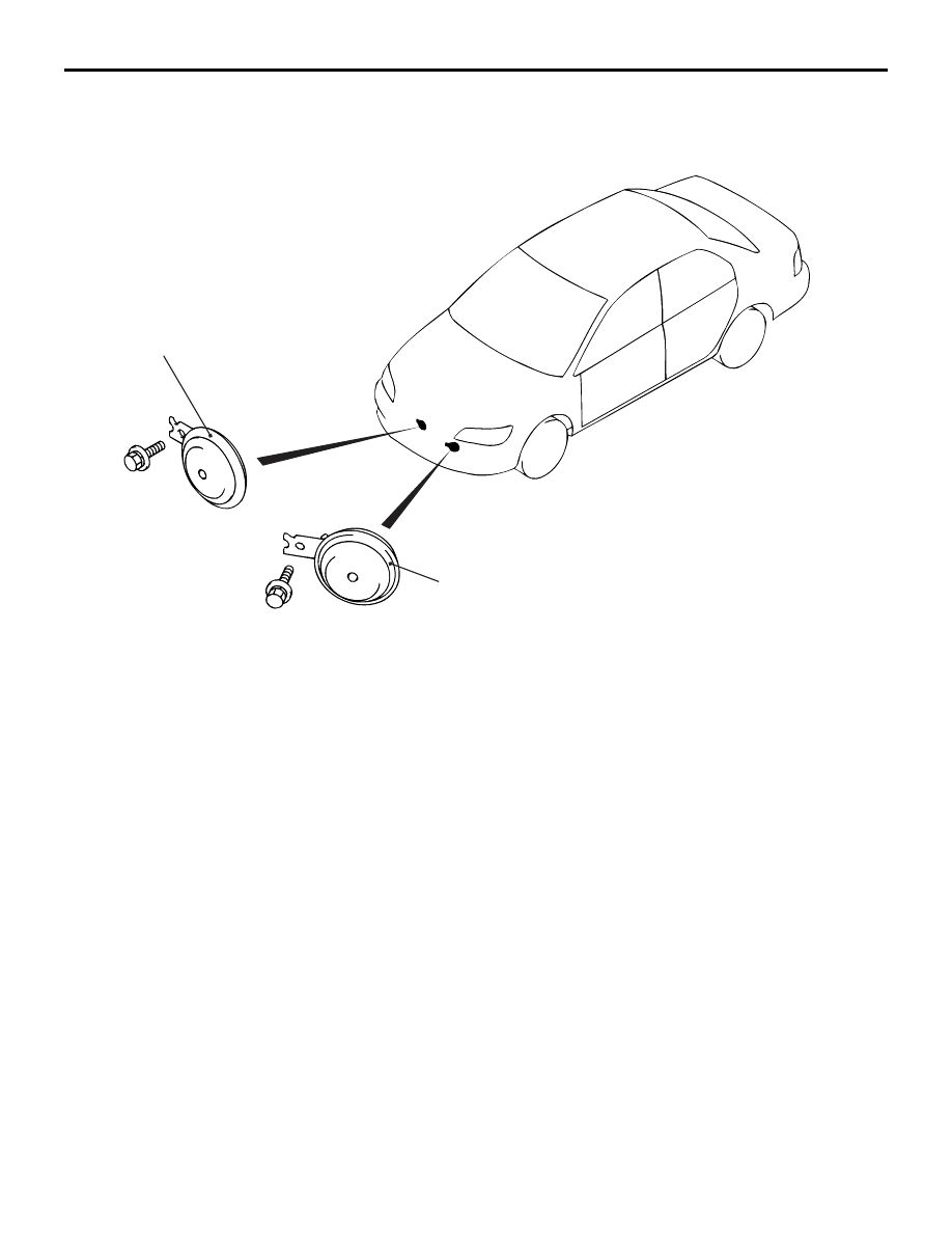
HORN
REMOVAL AND INSTALLATION
M1543007900479
AC211783AC
1
2
Removal Steps
1. Horn <LO>
2. Horn <HI>

CLOCK
CHASSIS ELECTRICAL
54A-76
HORN RELAY CONTINUITY CHECK
M1543019502418
AC305306
1
4
3
2
AB
Horn relay
Battery voltage
Tester
connection
Specified
condition
Not applied
1
− 4
Open circuit
• Connect terminal
2 to the positive
battery terminal
• Connect terminal
3 to the negative
battery terminal
1
− 4
Less than 2
ohms
CLOCK
SPECIAL TOOL
M1543000601663
Tool
Number
Name
Use
MB990784
MB990784
Ornament remover Removal of centre panel and
centre air outlet panel
Нет комментариевНе стесняйтесь поделиться с нами вашим ценным мнением.
Текст