Mitsubishi Lancer Evolution IX. Manual — part 285
CIGARETTE LIGHTER
CHASSIS ELECTRICAL
54A-77
CLOCK
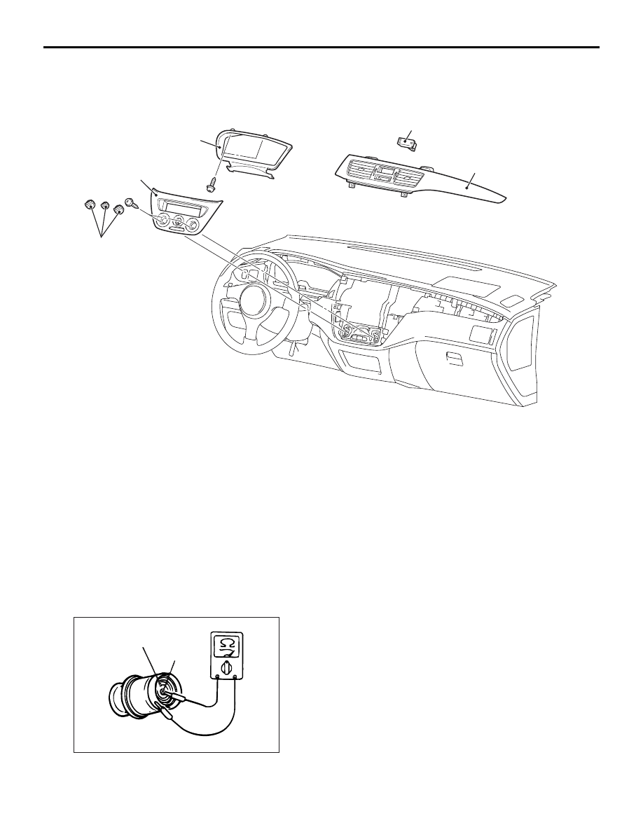
REMOVAL AND INSTALLATION
M1543005900309
AC211606AC
3
4
2
5
1
Removal steps
1. Knob
2. Centre panel
3. Meter bezel
4. Centre air outlet panel
5. Clock
CIGARETTE LIGHTER
INSPECTION
M1543005700242
CIGARETTE LIGHTER CHECK
ACX01832AE
Element
Spot
• Take out the plug, and check for a worn edge on
the element spot connection, and for shreds of
tobacco or other material on the element.
• Using an ohmmeter, check that the element
resistance value is 1.7 ohms.
Removal steps (Continued)

SPEAKER
CHASSIS ELECTRICAL
54A-78
SPEAKER
REMOVAL AND INSTALLATION
M1544002600573
AC211402
1
3
2
1.5 ± 0.5 N·m
1.5 ± 0.5 N·m
4
5
<Tweeter>
<Front speaker>
<Rear speaker>
AC
1.5 ± 0.5 N·m
Tweeter removal steps
•
Front pillar trim (Refer to GROUP
52A, Trims
1.
Tweeter
Front speaker removal steps
2.
Front door trim (Refer to GROUP
52A, Door trim
3.
Front speaker
Rear speaker removal steps
4.
Rear speaker garnish
5.
Rear speaker

ANTENNA
CHASSIS ELECTRICAL
54A-79
ANTENNA
REMOVAL AND INSTALLATION
M1544002900648
Pre-removal and Post-installation Operation
• Front pillar trim, Rear pillar trim, Centre pillar trim lower,
Centre pillar trim upper (Refer to GROUP 52A, Trims
• Headlining Removal and Installation (Refer to GROUP
52A, Headlining
AC005156AD
1
2
3
1. Roof antenna pole
Antenna feeder cable removal steps
2. Roof antenna base
•
Instrument panel assembly (Refer to
GROUP 52A, Instrument panel assembly
).
3. Antenna feeder cable
REAR WINDOW DEFOGGER
GENERAL INFORMATION
M1543000100319
Rear Defogger operation
The defogger relay turns ON if the defogger switch
built-in the A/C-ECU is turned ON when the ignition
switch is in the "ON" position. When the defogger
relay turns ON, power is supplied to the defogger
and the defogger is activated. The defogger comes
with a timer function that causes the defogger switch
to automatically turn OFF in about 11 minutes after
the defogger switch is turned ON.
TROUBLESHOOTING
M1543000701552
The rear window defogger is controlled by the
A/C-ECU. For troubleshooting, refer to GROUP 55-
Troubleshooting

REAR WINDOW DEFOGGER
CHASSIS ELECTRICAL
54A-80
ON-VEHICLE SERVICE
PRINTED HEATER LINES CHECK
M1543001800311
AC407247
Voltage (V)
Voltage (V)
12
6
12
6
Open circuit point
AC
Normal characteristic curve
A (Centre point)
Approximately 6 V
Positive
terminal
Negative
terminal
Print heater line
Positive
terminal
Negative
terminal
Print heater line
Abnormal characteristic curve
1. Run engine at 2,000 r/min. Check heater element
with battery at full.
2. Turn "ON" rear window defogger switch. Measure
heater element voltage with circuit tester at rear
window glass centre A. Condition is good if it
indicates about six volts.
3. If 12 volts is indicated at A, there is a break in the
negative terminals from A. Move test bar slowly to
negative terminal to detect where voltage
changes suddenly (0 volts).
4. If 0 volts is indicated at A, there is a break in the
positive terminals from A. Defect where the
voltage changes suddenly (12 volts) in the same
method described above.
REAR WINDOW DEFOGGER SWITCH
REMOVAL AND INSTALLATION
M1543006200314
Refer to GROUP 55, Heater Control Assembly and
A/C Switch
INSPECTION
M1543019502816
DEFOGGER RELAY CHECK
1
5
4
3
AC305319AC
Rear window defogger relay
Battery voltage
Tester
connection
Specified
condition
Not supplied
4
− 5
Open circuit
• Connect terminal
3 to the positive
battery terminal
• Connect terminal
1 to the negative
battery terminal
4
− 5
Less than 2
ohms
Нет комментариевНе стесняйтесь поделиться с нами вашим ценным мнением.
Текст