Mitsubishi Lancer Evolution IX. Manual — part 335

CRANKSHAFT OIL SEAL
ENGINE MECHANICAL
11A-29
CRANKSHAFT OIL SEAL
REMOVAL AND INSTALLATION
M1112003100444
CAUTION
If the vehicle is equipped with the Brembo
™ disc brake, during maintenance, take care not to contact
the parts or tools to the caliper because the paint of caliper will be scratched.
AC210943
AB
1
2
3
(Lip section)
Engine oil
3
6
6
5
4
N
N
132 ± 5 N·m
(Lip section)
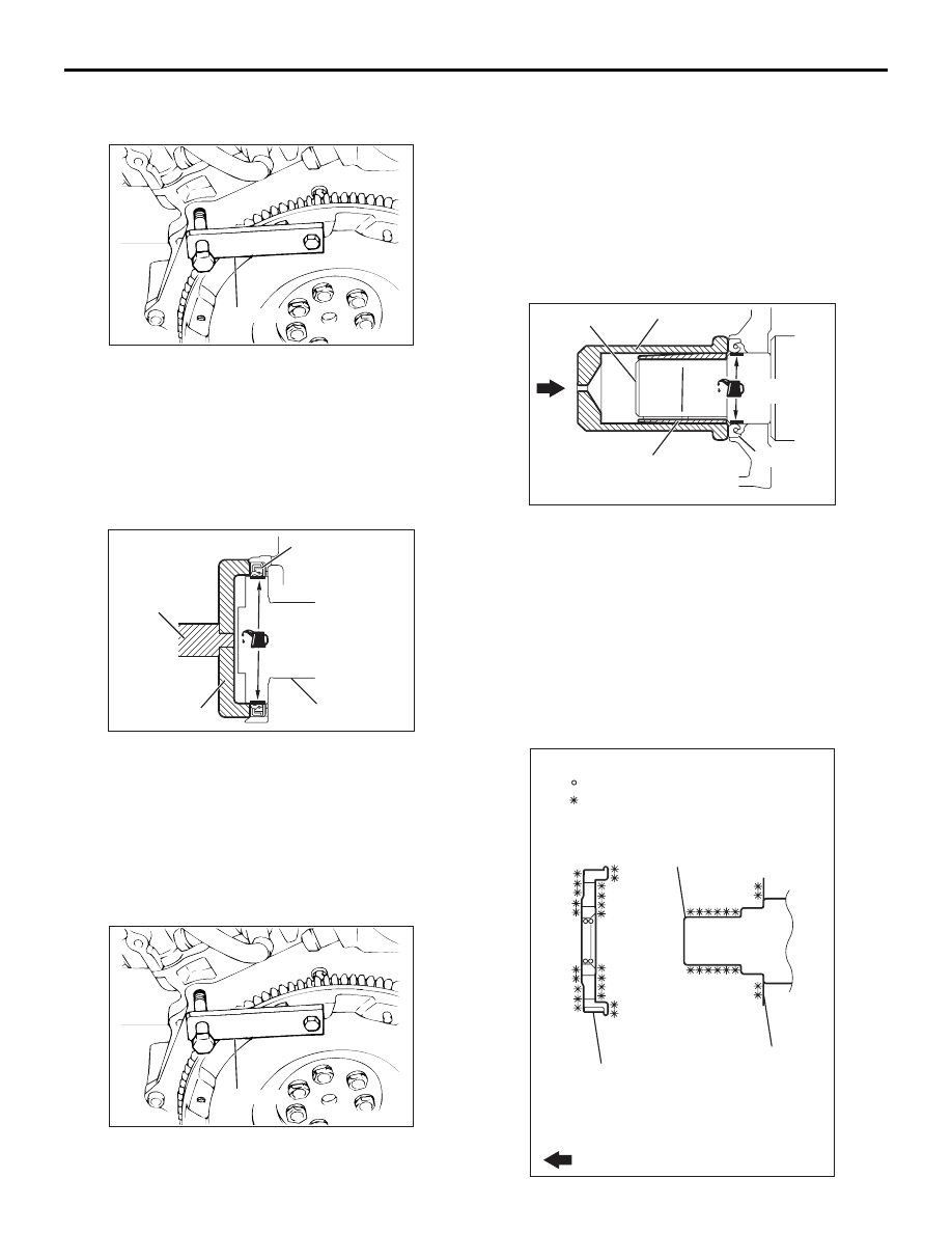
Crankshaft front oil seal removal
steps
•
Valve timing belt, balancer timing
belt (Refer to
).
>>
D
<<
1.
Crankshaft balancer shaft drive
sprocket
2.
Crankshaft key
>>
C
<<
3.
Crankshaft front oil seal
Crankshaft front oil seal removal
steps
•
Transfer assembly (Refer to
GROUP 22A, Transfer Assembly
).
•
Transmission assembly (Refer to
GROUP 22A, Transmission
Assembly
).
<<
A
>>
>>
B
4.
Flywheel bolts
5.
Flywheel assembly
>>
A
6.
Crankshaft rear oil seal
CRANKSHAFT OIL SEAL
ENGINE MECHANICAL
11A-30
REMOVAL SERVICE POINT
<<A>> FLYWHEEL BOLTS REMOVAL
AC211171AB
MD998781
1. Use special tool flywheel stopper (MD998781) to
secure the flywheel.
2. Remove the flywheel mounting bolts.
INSTALLATION SERVICE POINTS
>>A<< CRANKSHAFT REAR OIL SEAL
INSTALLATION
AC102328 AB
Oil seal
MB990938
MD998776
Crankshaft
(Engine oil)
1. Apply a small amount of engine oil to the entire
inner diameter of the oil seal lip.
2. Use the following special tools to press-fit the oil
seal.
• Installer bar (MB990938)
• Crankshaft rear oil seal installer (MD998776)
>>B<< FLYWHEEL BOLTS INSTALLATION
AC211171AB
MD998781
1. Use special tool flywheel stopper (MD998781) to
secure the flywheel in the same manner as
removal.
2. Tighten the flywheel mounting bolts to the
specified torque.
Tightening torque: 132
± 5 N⋅m
>>C<< CRANKSHAFT FRONT OIL SEAL
INSTALLATION
AC102329AC
MD998285
(Engine oil)
(Oil applied to the
circumference)
Oil seal
Crankshaft
MD998375
1. Apply a small amount of engine oil to the entire
inner diameter of the oil seal lip.
2. Apply a small amount of engine oil to the outer
diameter of special tool crankshaft front oil seal
guide (MD998285) and install it to the crankshaft.
3. Use special tool crankshaft front oil seal installer
(MD998375) to press-fit the oil seal.
>>D<< CRANKSHAFT BALANCER SHAFT
DRIVE SPROCKET INSTALLATION
AC211222
Crankshaft
balancershaft
drive sprocket
Engine front
Front case
Crankshaft
AB
: Clean
: Clean and degrease

CYLINDER HEAD GASKET
ENGINE MECHANICAL
11A-31
1. Clean or degrease the front case, the crankshaft
and the crankshaft balancer shaft drive sprocket
as shown.
NOTE: Also clean the degreased surfaces.
2. Install the crankshaft balancer shaft drive sprocket
in the direction shown in the illustration.
CYLINDER HEAD GASKET
REMOVAL AND INSTALLATION
M1112004001744
CAUTION
If the vehicle is equipped with the Brembo
™ disc brake, during maintenance, take care not to contact
the parts or tools to the caliper because the paint of caliper will be scratched.
Pre-removal Operation
• Fuel Line Pressure Reduction [Refer to GROUP 13A,
On-vehicle Service
− Fuel Pump Connector Disconnec-
tion (How to Reduce Pressurized Fuel Lines)
].
• Under Cover Removal (Refer to GROUP 51, Front
).
• Side Cover Removal
• Engine Coolant Draining (Refer to GROUP 14, On-vehicle
Service
− Engine Coolant Replacement
• Engine Oil Draining (Refer to GROUP 12, On-vehicle
Service
− Engine Oil Replacement
).
• Strut Tower Bar Removal (Refer to GROUP 42, Strut
Tower Bar
• Air Cleaner Assembly Removal (Refer to GROUP 15, Air
Cleaner
).
• Air Hose E, Air Pipe C and Air Hose D Removal (Refer to
GROUP 15, Intercooler
).
• Battery Removal
• Accelerator Cable Removal (Refer to GROUP 17, Accel-
erator Cable and Pedal
• Rocker Cover Centre Cover Removal (Refer to
• Radiator Assembly Removal (Refer to GROUP 14, Radia-
).
• Front Axle Crossmember Bar Removal (Refer to GROUP
32, Engine Roll Stopper and Centermember
• Front Exhaust Pipe Removal (Refer to GROUP 15,
Exhaust Pipe and Main Muffler
• Starter Assembly Removal (Refer to GROUP 16, Starter
Motor Assembly
).
• Valve Timing Belt Removal (Refer to
).
Post-installation Operation
• Valve Timing Belt Installation (Refer to
).
• Starter Assembly Installation (Refer to GROUP 16, Starter
Motor Assembly
).
• Front Exhaust Pipe Installation (Refer to GROUP 15,
Exhaust Pipe and Main Muffler
• Front Axle Crossmember Bar Installation (Refer to
GROUP 32, Engine Roll Stopper and Centermember
).
• Radiator Assembly Installation (Refer to GROUP 14,
Radiator
).
• Rocker Cover Centre Cover Installation (Refer to
• Accelerator Cable Installation (Refer to GROUP 17,
Accelerator Cable and Pedal
• Battery Installation
• Air Hose E, Air Pipe C and Air Hose D Installation (Refer
to GROUP 15, Intercooler
).
• Air Cleaner Assembly Installation (Refer to GROUP 15,
Air Cleaner
).
• Strut Tower Bar Installation (Refer to GROUP 42, Strut
Tower Bar
• Engine Oil Refilling (Refer to GROUP 12, On-vehicle
Service
− Engine Oil Replacement
).
• Engine Coolant Refilling (Refer to GROUP 14, On-vehicle
Service
− Engine Coolant Replacement
• Drive Belt Tension Check (Refer to
• Side Cover Installation
• Under Cover Installation (Refer to GROUP 51, Front
).
• Accelerator Cable Adjustment (Refer to GROUP 17,
On-vehicle Service
− Accelerator Cable Check and
Adjustment
).
• Fuel Leak Check
AC310567
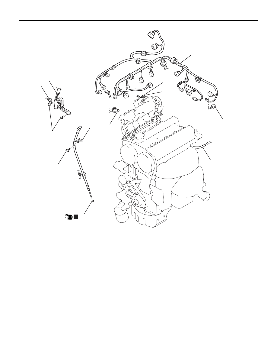
5.0 ± 1.0 N·m
AB
13 ± 1 N·m
5.0 ± 1.0 N·m
N
(Engine oil)
9.0 ± 1.0 N·m
7
4
3
6
5
2
8
1
Removal steps
1.
Control wiring harness connection
2.
Earth cable connection
3.
EGR solenoid valve connector
4.
EGR solenoid valve and bracket
assembly
5.
Brake booster vacuum hose
connection
6.
Oil level gauge and guide assembly
7.
O-ring
8.
Purge hose connection
CYLINDER HEAD GASKET
ENGINE MECHANICAL
11A-32
Removal steps (Continued)
Нет комментариевНе стесняйтесь поделиться с нами вашим ценным мнением.
Текст