Mitsubishi Lancer Evolution IX. Manual — part 333

CAMSHAFT AND VALVE STEM SEAL
ENGINE MECHANICAL
11A-21
<<C>> VALVE SPRING RETAINER LOCKS
REMOVAL
CAUTION
When removing valve spring retainer locks, leave
the piston of each cylinder in the TDC (Top Dead
Centre) position. The valve may fall into the cylin-
der if the piston is not properly in the TDC posi-
tion.
AC201799
MD998772
AB
Use special tool valve spring compressor
(MD998772) to compress the valve spring, remove
the valve spring retainer locks.
INSTALLATION SERVICE POINTS
>>A<< EXHAUST VALVE STEM
SEALS/INLET VALVE STEM SEALS
INSTALLATION
1. Apply a small amount of engine oil to the valve
stem seals.
CAUTION
• Valve stem seals cannot be reused.
•
AC308920AB
MD998737
Valve
Valve stem
seal
Valve guide
The special tool valve stem seal installer
(MD998737) must be used to install the valve
stem seal. Improper installation could result
in oil leaking past the valve guide.
2. Use the special tool to fill a new valve stem seal in
the valve guide using the valve stem area as a
guide.
AC201542
AB
Exhaust side
Inlet side
Grey
Grey green
NOTE: Check the valve stem seal colour to iden-
tify the inlet side or exhaust side.
>>B<< VALVE SPRINGS INSTALLATION
AC211159AB
Rocker arm side
Small end
The small end of the valve spring should face the
rocker arm.
>>C<< VALVE SPRING RETAINER LOCKS
INSTALLATION
AC201799
MD998772
AB
Use special tool valve spring compressor
(MD998772) to compress the valve spring in the
same manner as removal.

CAMSHAFT AND VALVE STEM SEAL
ENGINE MECHANICAL
11A-22
>>D<< ROCKER ARM LASH ADJUSTERS
INSTALLATION
CAUTION
If the rocker arm lash adjuster is reused, always
clean and check it before installation. (Refer to
GROUP 11B, Rocker Arms and Camshaft
−
Inspection
).
>>E<< EXHAUST CAMSHAFT/INLET
CAMSHAFT INSTALLATION
1. Remove sealant remained on the cylinder head.
2. Apply engine oil to the cam and the journal of the
camshaft.
CAUTION
Do not install wrong camshaft on the side of inlet
or exhaust. The exhaust camshaft has a slit at the
rear surface.
AC407425
Engine front
<Inlet side>
<Exhaust side>
Slit
Slit
AC
3. Install the camshaft to the cylinder head.
>>F<< CAMSHAFT BEARING CAPS, NO.
4/CAMSHAFT BEARING CAPS, NO.
3/CAMSHAFT BEARING CAPS, NO.
5/CAMSHAFT BEARING CAPS, NO.
2/CAMSHAFT BEARING CAPS,
REAR/CAMSHAFT BEARING CAPS,
FRONT INSTALLATION
AC201459AC
Dowel pin
Exhaust side
Inlet side
Approximately 4˚
1. Set the dowel pin of the camshaft to the position
as shown in the illustration.
AC201460
E 4
AB
Bearing
cap No.
Identification of
inlet side and
exhaust side
Engine front
2. Since the shape of camshaft bearing caps No.2
−
5 is identical, check the identification marks so
that the bearing cap No., inlet side, or exhaust
side is installed in the direction shown in the
illustration.
Identification mark (engraved on the front
and bearing caps No.2
− 5)
I: Inlet side
E: Exhaust side
AC201461AC
Engine front
3. Apply sealant to the positions (8 areas) of the
upper side of the cylinder head as shown in the
illustration.
Specified sealant: MITSUBISHI GENUINE
PART MD970389 or equivalent

AC406643
AE
<Inlet side>
Engine front
Front
marking
AC406642
AF
<Exhaust side>
Engine front
Front
marking
CAMSHAFT AND VALVE STEM SEAL
ENGINE MECHANICAL
11A-23
4. Position the camshaft bearing caps, rear in the
direction as shown in the illustration for
installation.
5. Check the identification marks on the camshaft
bearing caps, front so that inlet side and exhaust
side is installed in the same way as that of bearing
caps No.2
− 5.
6. Tighten the bearing cap mounting bolts increasing
the pressure in 2 to 3 times and finally tighten to
the specified torque.
Tightening torque: 20
± 1 N⋅m
7. Ensure that the rocker arms are installed properly.
NOTE: Remove an excess sealant completely.
>>G<< CAMSHAFT OIL SEALS
INSTALLATION
AC102323AB
MD998713
1. Apply engine oil to the entire inner diameter of the
oil seal lip.
2. Use special tool camshaft oil seal installer
(MD998713) to press-fit the oil seals.
>>H<< CAMSHAFT SPROCKET (INLET
SIDE) INSTALLATION
AC500123AC
Engine front
Camshaft
sprocket
(Engine oil)
1. Apply engine oil to the tip of the camshaft and the
camshaft installation side of the camshaft
sprocket.
2. Align the dowel pin hole of the camshaft sprocket
with the dowel pin of the camshaft, and install the
camshaft sprocket to the camshaft.
3. While holding the hexagonal area of the camshaft
with a wrench, check that the camshaft sprocket
does not turn.
NOTE: This is necessary, because you cannot
confirm that the camshaft dowel pin is inserted
into the pin hole.
AC504842AB
Engine front
Camshaft
sprocket
(Engine oil)
4. Apply the engine oil to the threads and the face of
the camshaft sprocket mounting bolt. Then fix the
camshaft with a wrench in the same way as
removal and tighten the camshaft sprocket
mounting bolt to the specified torque.
Tightening torque: 65
± 5 N⋅m
CAMSHAFT AND VALVE STEM SEAL
ENGINE MECHANICAL
11A-24
>>I<< CAMSHAFT SPROCKET (EXHAUST
SIDE) INSTALLATION
AC407095AC
1. Hold the hexagon part of the camshaft with a
wrench in the same manner as removal.
2. Tighten the camshaft sprocket mounting bolts to
the specified torque.
Tightening torque: 89
± 9 N⋅m
>>J<< CAMSHAFT POSITION SENSOR
SUPPORT INSTALLATION
1. Remove sealant from the camshaft position
sensor support and cylinder head surfaces.
AC201463
3 mm
AC
<Exhaust side>
AC406663
3 mm
AC
<Inlet side>
2. Apply the sealant to the camshaft position sensor
support flange in a continuous bead as shown in
the illustration.
Specified sealant: MITSUBISHI GENUINE
PART MD970389 or equivalent
NOTE: Install the camshaft position sensor sup-
port within 15 minutes after applying liquid gasket.
3. Install the camshaft position sensor support to the
cylinder head.
CAUTION
Wait at least one hour. Never start the engine or
let engine oil or coolant touch the adhesion sur-
face during that time.
4. Tighten the camshaft position sensor support
mounting bolts to the specified torque.
Tightening torque: 14
± 1 N⋅m
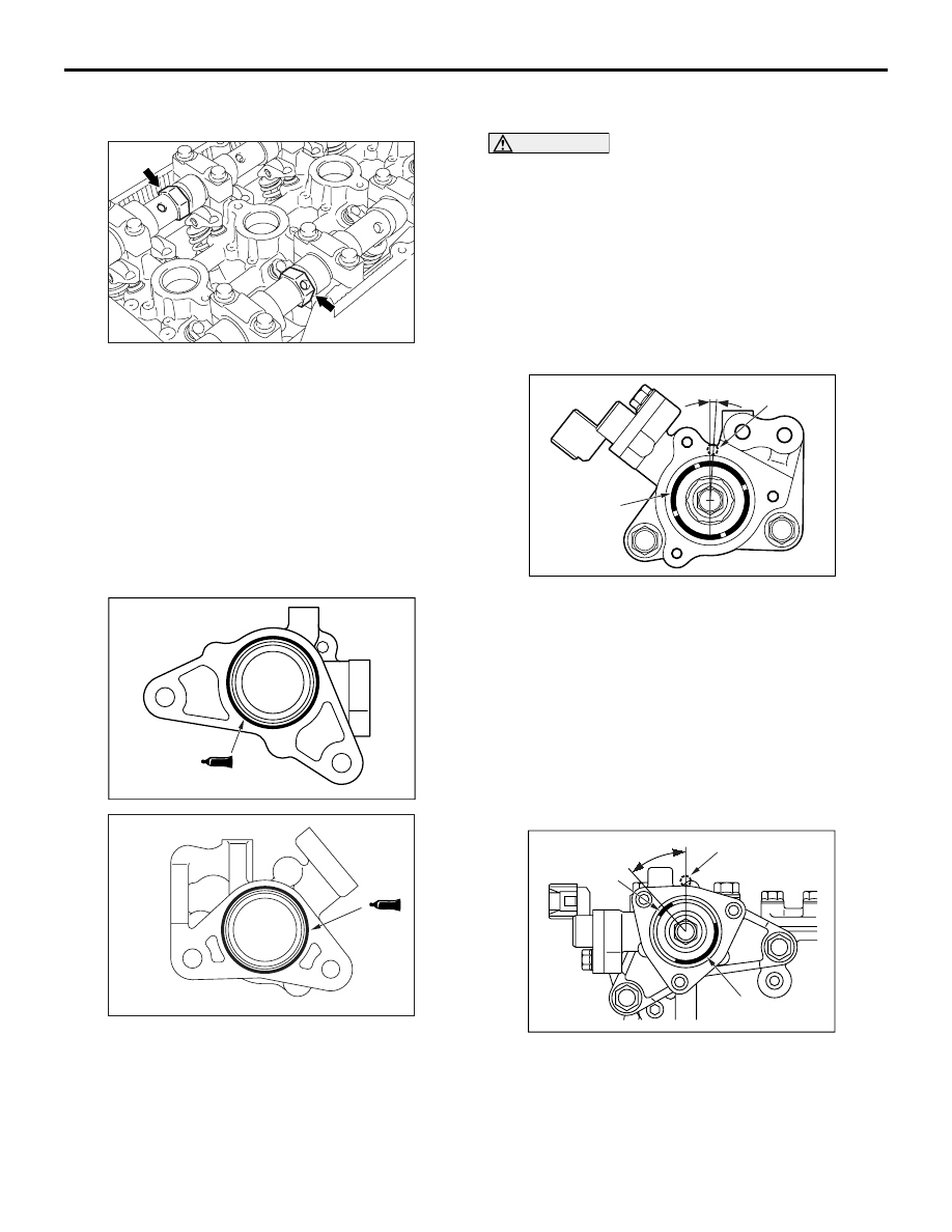
>>K<< CAMSHAFT POSITION SENSING
CYLINDER (INLET SIDE) INSTALLATION
AC406644
AE
(4˚ 1')
Dowel pin
Vane
1. Set the dowel pin of the inlet camshaft to the
position (No.1 cylinder at compression TDC) as
shown in the illustration.
2. Tighten the camshaft position sensing cylinder
mounting bolts to the specified torque.
Tightening torque: 22
± 4 N⋅m
>>L<< CAMSHAFT POSITION SENSING
CYLINDER (EXHAUST SIDE)
INSTALLATION
AC201464AB
Dowel pin
Vane (large)
Vane (small)
Approximately 45˚
1. Set the dowel pin of the exhaust camshaft to the
position (No.1 cylinder at compression TDC) as
shown in the illustration.
NOTE: Use the force of the exhaust valve spring
to rotate anti-clockwise.
Нет комментариевНе стесняйтесь поделиться с нами вашим ценным мнением.
Текст