Mitsubishi Lancer Evolution IX. Manual — part 339

AC102339AB
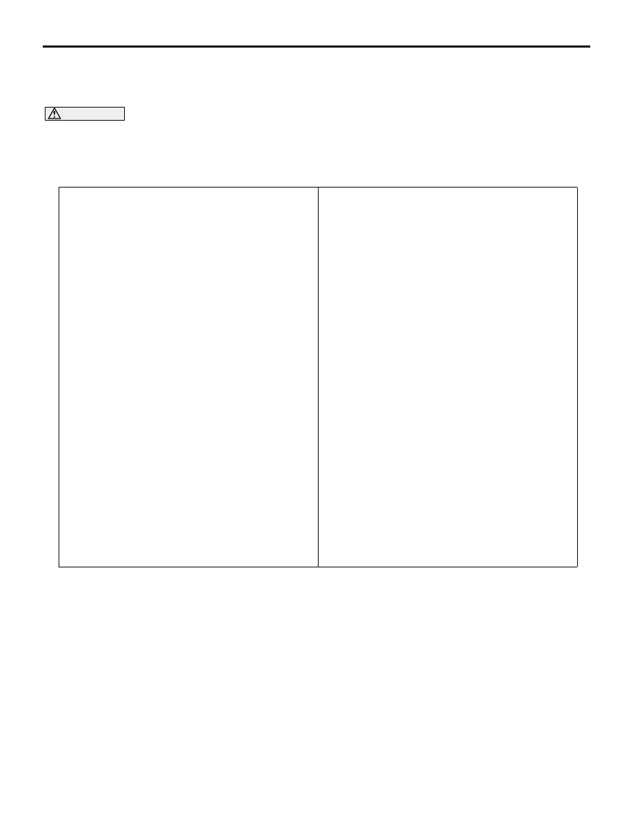
98 – 196 N
Rod
Timing belt
tensioner
adjuster
Movement
B
A
TIMING BELT
ENGINE MECHANICAL
11A-45
3. Hold the timing belt tensioner adjuster by hand,
and press the top end of the rod onto the metal
(e.g. cylinder block) under a pressure of 98
− 196
N to measure the movement of the rod.
Standard value: Within 1 mm
A: Length when it is free (not pressed)
B: Length when it is pressed
A
− B: Movement
4. If the measured value is out of the standard value,
replace the timing belt tensioner adjuster.
BALANCER TIMING BELT TENSION
CHECK
Check the balancer timing belt tension as follows:
AC102693AB
Deflection
Approximately 100 N
1. Apply a pressure of approximately 100N at the
centre (arrow area) between the sprocket as
shown then inspect whether the deflection is
within the standard value.
Standard value: 5
− 10 mm
2. If not within the standard value, adjust the belt
tension.
(Refer to
).
ENGINE ASSEMBLY
ENGINE MECHANICAL
11A-46
ENGINE ASSEMBLY
REMOVAL AND INSTALLATION
M1112001002317
CAUTION
• If the vehicle is equipped with the Brembo™ disc brake, during maintenance, take care not to con-
tact the parts or tools to the caliper because the paint of caliper will be scratched.
•
Pre-removal Operation
• Fuel Line Pressure Reduction [Refer to GROUP 13A,
On-vehicle Service
− Fuel Pump Connector Disconnec-
tion (How to Reduce Pressurized Fuel Lines)
].
• Hood Removal (Refer to GROUP 42, Hood
• Under Cover Removal (Refer to GROUP 51, Front
).
• Side Cover Removal
• Engine Oil Draining (Refer to GROUP 12, On-vehicle
Service
− Engine Oil Replacement
).
• Engine Coolant Draining (Refer to GROUP 14, On-vehicle
Service
− Engine Coolant Replacement
• Strut Tower Bar Removal (Refer to GROUP 42, Strut
Tower Bar
• Air Cleaner Assembly Removal (Refer to GROUP 15, Air
Cleaner
).
• Air Pipe C, Air Pipe B and Air Hose A Removal (Refer to
GROUP 15, Intercooler
).
• Battery and Battery Tray Removal
• Accelerator Cable Removal (Refer to GROUP 17, Accel-
erator Cable and Pedal
• Rocker Cover Centre Cover Removal (Refer to
• Radiator Assembly Removal (Refer to GROUP 14, Radia-
).
• Front Axle Crossmember Bar Removal (Refer to GROUP
32, Engine Roll Stopper and Centermember
• Front Exhaust Pipe Removal (Refer to GROUP 15,
Exhaust Pipe and Main Muffler
• Air Outlet Fitting Removal (Refer to GROUP 15, Exhaust
Manifold and Turbocharger
Post-installation Operation
• Air Outlet Fitting Installation (Refer to GROUP 15,
Exhaust Manifold and Turbocharger
).
• Front Exhaust Pipe Installation (Refer to GROUP 15,
Exhaust Pipe and Main Muffler
• Front Axle Crossmember Bar Installation (Refer to
GROUP 32, Engine Roll Stopper and Centermember
).
• Radiator Assembly Installation (Refer to GROUP 14,
Radiator
).
• Rocker Cover Centre Cover Installation (Refer to
• Accelerator Cable Installation (Refer to GROUP 17,
Accelerator Cable and Pedal
• Battery and Battery Tray Installation
• Air Pipe C, Air Pipe B and Air Hose A Installation (Refer to
GROUP 15, Intercooler
).
• Air Cleaner Assembly Installation (Refer to GROUP 15,
Air Cleaner
).
• Strut Tower Bar Installation (Refer to GROUP 42, Strut
Tower Bar
• Engine Coolant Refilling (Refer to GROUP 14, On-vehicle
Service
− Engine Coolant Replacement
• Engine Oil Refilling (Refer to GROUP 12, On-vehicle
Service
− Engine Oil Replacement
).
• Drive Belt Tension Check (Refer to
• Side Cover Installation
• Under Cover Installation (Refer to GROUP 51, Front
).
• Accelerator Cable Adjustment (Refer to GROUP 17,
On-vehicle Service
− Accelerator Cable Check and
Adjustment
).
• Hood Installation (Refer to GROUP 42, Hood
).
• Fuel Leak Check
*: indicates parts which should be temporarily tightened, and then fully tightened with the engine
weight applied on the vehicle body.

AC310569
5.0 ± 1.0 N·m
26 ± 5 N·m
AB
11 ± 1 N·m
14 ± 3 N·m
5.0 ± 1.0 N·m
4
1
5
3
2
5.0 ± 1.0 N·m
Removal steps
1.
Control wiring harness connection
2.
Earth cable connection
3.
Battery wiring harness connection
4.
Turbocharger wastegate actuator
bolts
<<
A
>>
5.
Drive belt
ENGINE ASSEMBLY
ENGINE MECHANICAL
11A-47
Removal steps (Continued)

AC211078 AC
12 ± 2 N·m
22 ± 4 N·m
40 ± 5 N·m
22 ± 4 N·m
N
98 ± 10 N·m*
N
67 ± 7 N·m*
42 ± 2 N·m
42 ± 2 N·m
5.0 ± 1.0 N·m
19
18
17
16
15
14
13
12
10
9
8
7
6
11
22
N
(Engine oil)
20
21
Removal steps
6.
Brake booster vacuum hose
connection
7.
Purge hose connection
8.
Power steering pressure switch
connector
9.
Power steering oil pump heat
protector
<<
B
>>
10. Power steering oil pump, bracket
and reservoir assembly
11. A/C compressor connector
<<
B
>>
12. A/C compressor and clutch
assembly
13. Engine oil cooler feed hose
connection
14. Engine oil cooler tube gaskets
15. Engine oil cooler return hose
connection
16. Engine oil cooler tube gaskets
17. Heater water hoses connection
18. Fuel return line hose connection
>>
D
19. Fuel high-pressure hose
connection
>>
D
20. O-ring
•
Transfer assembly (Refer to
GROUP 22A, Transfer Assembly
).
<<
C
>>
>>
C
•
Transmission assembly
<<
D
>>
>>
B
21. Engine mounting insulator and
cushion stoppers assembly
<<
E
>>
A
22. Engine assembly
ENGINE ASSEMBLY
ENGINE MECHANICAL
11A-48
Removal steps (Continued)
Нет комментариевНе стесняйтесь поделиться с нами вашим ценным мнением.
Текст