Mitsubishi Montero (1991+). Manual — part 63
ACTUATOR TESTS
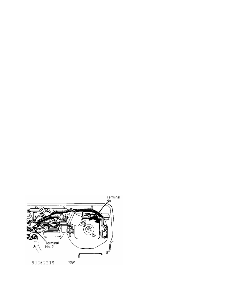
Resistance Test (1991)
Disconnect actuator connector. Resistance between terminals
No. 1 and 2 should be 20 ohms. See Figs. 17-21. If resistance is not
correct, replace actuator assembly.
Operational Test (1991)
1) With connector disconnected, connect battery voltage to
terminal No. 1. See Figs. 17-21. Ground terminal No. 2. Connect
ammeter between positive side of battery and terminal No. 1 of
actuator connector.
2) Solenoid should make a click sound. Ammeter should read .
5-.7 amps. Connect positive side of battery to terminal No. 4 and
ground terminal No. 3. Actuator should pull in and stop.
3) While actuator is moving in, ammeter should read less than
.5 amps. When actuator travel reaches midpoint, disconnect terminal
No. 1 from positive side of battery. Actuator should return to
original position. If actuator does not test correctly, replace
actuator.
4) Reverse connections of terminals No. 4 and 3 in step 2).
Connect battery voltage to terminal No. 3 and ground terminal No. 4.
Actuator should move out then stop. While actuator is moving, ammeter
should read less than .5 amps.
1992
Remove actuator. Apply vacuum to actuator. Actuator linkage
holder should move more than 1.38" (35 mm). Actuator diaphragm should
hold vacuum. Replace actuator if actuator does not test correctly.
VEHICLE SPEED SENSOR TEST
1) Remove instrument cluster. See INSTRUMENT CLUSTER under
REMOVAL & INSTALLATION. Check continuity between vehicle speed sensor
terminals at instrument cluster. See Fig. 30 or 31.
2) Ensure continuity pulses on and off 4 times per revolution
of speedometer shaft connection. If continuity is not as specified,
replace vehicle speed sensor.
Fig. 30: 1991 Checking Speed Sensor Circuit
Courtesy of Mitsubishi Motor Co.
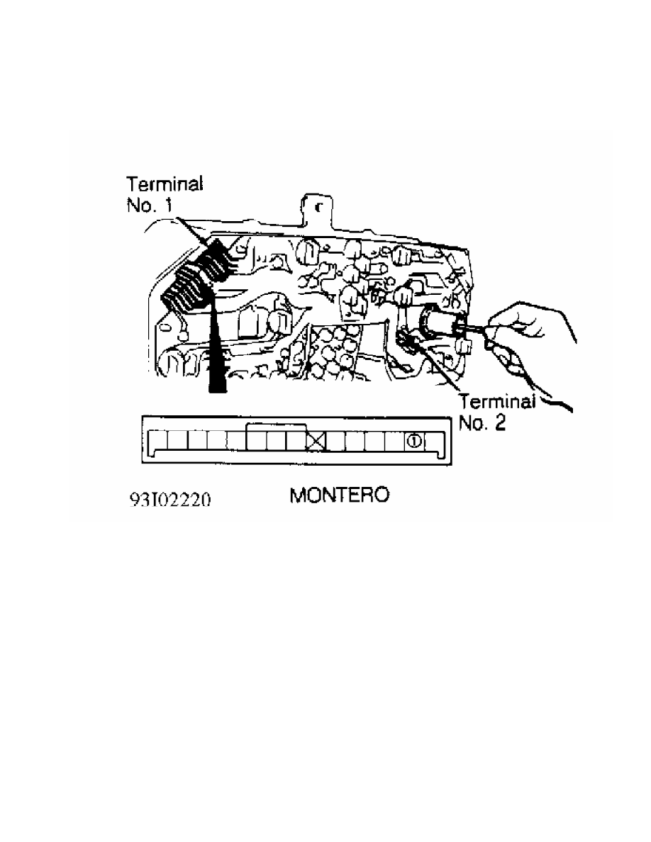
Fig. 31: 1992 Checking Speed Sensor Circuit
Courtesy of Mitsubishi Motor Co.
REMOVAL & INSTALLATION
ACTUATOR
Removal & Installation (1991)
Remove linkage protector. Loosen adjusting nuts for
accelerator cables "A" and "B". See Fig. 1 or 2. Disconnect actuator
side inner cable. Disconnect actuator electrical connector. Remove
actuator. To install, reverse removal procedure.
Removal & Installation (1992)
Disconnect cruise control cable from link. Disconnect
actuator wiring connector. Remove vacuum pump and vacuum pump bracket.
Remove actuator and actuator bracket. To install, reverse removal
procedure.
CRUISE CONTROL SWITCH
Removal & Installation (1991)
See STEERING COLUMN SWITCH in this article.
Removal & Installation (1992)
Remove lower steering column cover. Disconnect electrical
connectors. Remove screws attaching cruise control switch to steering
column. Remove switch. To install, reverse removal procedure.
STEERING COLUMN SWITCH
WARNING: DO NOT hammer steering wheel. Collapsible steering column
mechanism may be damaged.
Removal & Installation (1991)
Remove horn pad and steering wheel. Remove upper and lower
column covers. Remove column switch. To install, reverse removal
procedure.
VEHICLE SPEED SENSOR
Removal & Installation
Remove instrument cluster. See INSTRUMENT CLUSTER in this
article. Speed sensor is a part of speedometer.
INSTRUMENT CLUSTER
Removal & Installation
Disconnect negative battery cable. Remove cluster cover.
Disconnect speedometer cable. Remove instrument cluster. To install,
reverse removal procedure.
CONTROL UNIT
Removal & Installation (1991)
Cruise control unit is located behind left front kick panel.
Remove left front kick panel. Remove control unit. To install, reverse
removal procedure.
Removal & Installation (1992)
Cruise control unit is located behind center of dash panel.
Remove center trim panel and radio or radio plug bezel. Remove control
unit. To install, reverse removal procedure.
WIRING DIAGRAMS
For 1992 wiring diagram, See appropriate chassis wiring
diagram in the WIRING DIAGRAMS Section.
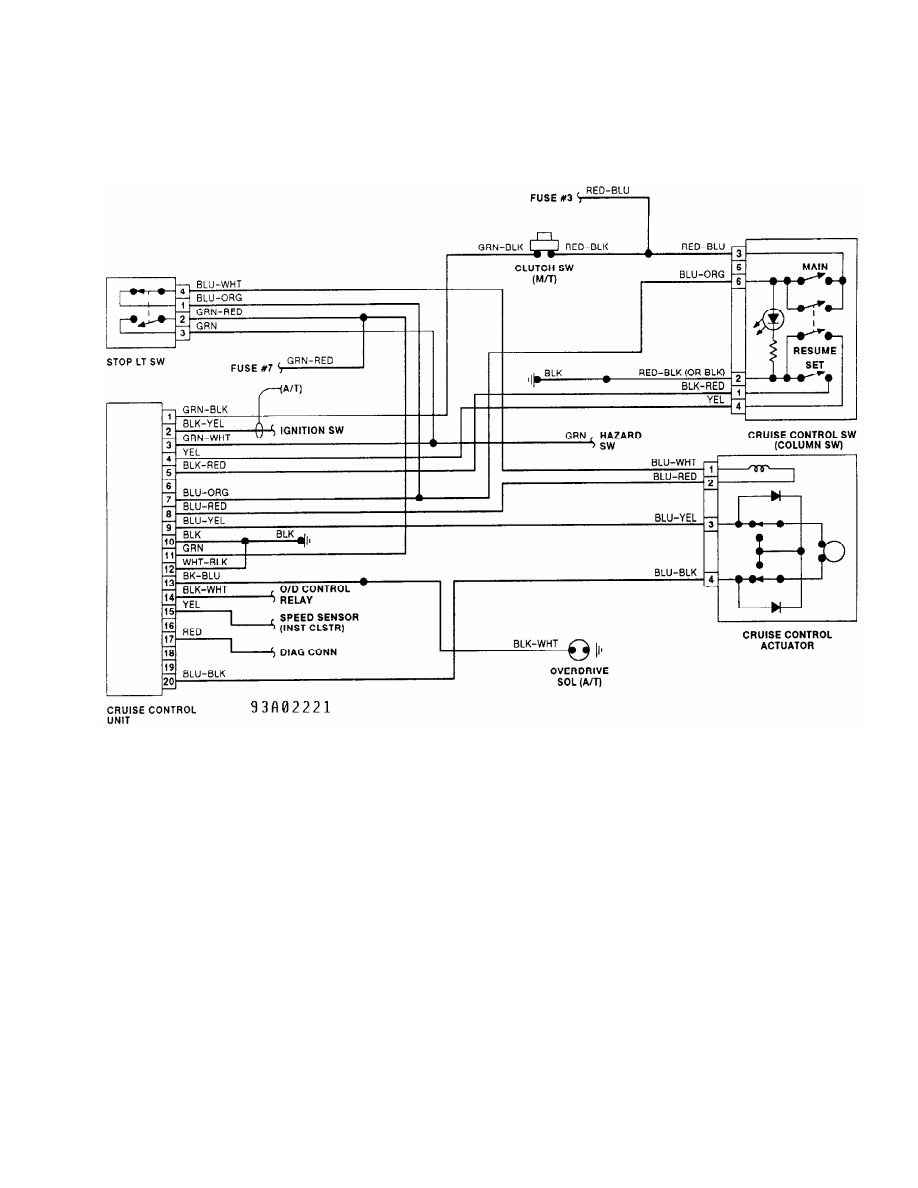
Fig. 32: 1991 Cruise Control System Wiring Diagram
Courtesy of Mitsubishi Motor Co.
Нет комментариевНе стесняйтесь поделиться с нами вашим ценным мнением.
Текст