Mitsubishi Montero (1991+). Manual — part 61

Fig. 19: 1991 Cruise Control Switch Connector
Courtesy of Mitsubishi Motor Co.
Fig. 20: 1991 Stoplight Switch Connector
Courtesy of Mitsubishi Motor Co.

Fig. 21: 1991 Acturator Connector
Courtesy of Mitsubishi Motor Co.
CIRCUIT TESTS (1992)
NOTE: To identify circuit connector terminals, See Figs. 22-29.
For wiring diagram, See appropriate chassis wiring diagram in
the WIRING DIAGRAMS Section.
Test No. 1 (Power & Ground Circuit)
1) Turn ignition on. When cruise control main switch is
turned to ON position, battery voltage should be present on terminal
No. 2 of cruise control unit connector.
2) If voltage is not present, check fuse No. 11 and replace
as necessary. If fuse is okay, check and repair harness as necessary.
Terminal No. 8 should be grounded at all times. If terminal No. 8 is
not grounded, repair harness.
Test No. 2 (Set Switch Circuits)
When set switch is turned to ON position, 3 volts should be
present on terminal No. 18 of cruise control unit. When set switch is
turned to OFF position, voltage should not be present on terminal No.
18 of cruise control unit. If circuit does not test correctly, replace
switch as necessary or repair harness.
Test No. 3 (Resume Switch Circuit)
When resume switch is turned to ON position, 6 volts should
be present on terminal No. 18 of cruise control unit. When resume
switch is turned to OFF position, voltage should not be present on
terminal No. 18 of cruise control unit. If circuit does not test
correctly, replace switch as necessary or repair harness.
Test No. 4 (Cancel Switch Circuit)
When cancel switch is turned to On position, battery voltage
should be present on terminal No. 18 of cruise control unit. When
cancel switch is in Off position, voltage should not be present on
terminal No. 18 of cruise control unit. If circuit does not test
correctly, replace switch as necessary or repair harness.

Test No. 5 (Vehicle Speed Sensor Circuit)
When vehicle moves slowly, 0-2 or more volts should alternate
at terminal No. 19 of cruise control unit. If circuit does not test
correctly, replace sensor as necessary or repair harness.
Test No. 6 (Vacuum Pump Circuit)
1) When cruise system is in deceleration or release mode,
battery voltage should be present on terminals No. 26 and 13 of cruise
control unit. If circuit does not test correctly, replace vacuum pump
as necessary or repair harness.
2) When cruise system is in release mode, battery voltage
should be present on terminal No. 12 of cruise control unit. When
cruise system is in hold mode, voltage on terminals No. 12, 13 and 26
will go from battery voltage to zero volts depending on driving
conditions. If circuit does not test correctly, replace vacuum pump as
necessary or repair harness.
Test No. 7 (Stoplight Switch Circuit)
When brake pedal is pressed, battery voltage should be
present on terminal No. 15 of cruise control unit. If voltage is not
present, adjust or replace brake switch. If circuit does not test
correctly, replace switch as necessary or repair harness.
Test No. 8 (Clutch Switch Circuit)
When clutch pedal is pressed, battery voltage should be
present at terminal No. 1 of cruise control unit. If circuit does not
test correctly, replace switch as necessary or repair harness.
Test No. 9 (Inhibitor Switch Circuit)
When transmission is in Neutral position, battery voltage
should be present on terminal No. 1 of cruise control unit. If circuit
does not test correctly, replace switch as necessary or repair
harness.
Test No. 10 (Overdrive Switch Circuit)
When overdrive switch is pushed to ON position, battery
voltage should be present on terminal No. 11 of cruise control unit.
If circuit does not test correctly, replace switch as necessary or
repair harness.
Test No. 11 (Idle Switch & Throttle Position Sensor Circuit)
1) When accelerator pedal is pressed, 4.5-5.5 volts should be
present on terminal No. 4 (idle switch) of cruise control unit. When
accelerator pedal is released, voltage should not be present on
terminal No. 4 of cruise control unit.
2) When accelerator pedal is pressed to wide open throttle,
4.0-5.5 volts should be present on terminal No. 5 (throttle position
sensor) of cruise control unit. When accelerator pedal is released, .
5-.7 volts should be present on terminal No. 5 of cruise control unit.
If circuit does not test correctly, replace sensor as necessary or
repair harness.
Fig. 22: 1992 Cruise Control Unit Connector
Courtesy of Mitsubishi Motor Co.
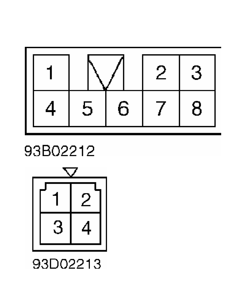
Fig. 23: 1992 Main Cruise Control Switch Connector
Courtesy of Mitsubishi Motor Co.
Fig. 24: 1992 Stoplight Switch Connector
Courtesy of Mitsubishi Motor Co.
Нет комментариевНе стесняйтесь поделиться с нами вашим ценным мнением.
Текст