Mitsubishi Montero (1991+). Manual — part 194
Application In. (mm)
Montero
Left Side . . . . .. 5.3-5.6 (135-142)
Right Side . . . . . 4.9-5.2 (124-132)
Ram-50 & Pickup
Left Side . . . . .. 5.5-5.8 (140-147)
Right Side . . . . . 5.3-5.6 (135-142)
5) After initial torsion bar setting, tighten anchor bolt
adjusting nut to obtain correct final bolt protrusion.
6) On Montero, final bolt protrusion depends upon curb weight
of vehicle. Adjust anchor bolt adjusting nut to obtain final anchor
bolt protrusion. See appropriate FINAL ANCHOR BOLT PROTRUSION table.
FINAL ANCHOR BOLT PROTRUSION TABLE (MONTERO)
Curb Weight Right Bolt Left Bolt
Lbs. (kg) In. (mm) In. (mm)
2910 (1320) . . ... 2.6 (65) . . . .. 2.2 (55)
3000 (1360) . . ... 2.7 (68) . . . .. 2.2 (55)
3080 (1400) . . ... 2.8 (71) . . . .. 2.3 (57)
3170 (1440) . . ... 2.8 (71) . . . .. 2.4 (59)
3260 (1480) . . ... 2.9 (72) . . . .. 2.5 (62)
3350 (1520) . . ... 3.0 (76) . . . .. 2.5 (62)
3440 (1560) . . ... 3.0 (76) . . . .. 2.6 (65)
3530 (1600) . . ... 3.1 (78) . . . .. 2.6 (65)
3620 (1640) . . ... 3.2 (80) . . . .. 2.7 (68)
3700 (1680) . . ... 3.2 (80) . . . .. 2.8 (71)
3790 (1720) . . ... 3.3 (84) . . . .. 2.9 (72)
3880 (1760) . . ... 3.4 (86) . . . .. 2.9 (72)
3970 (1800) . . ... 3.4 (86) . . . .. 3.0 (76)
4060 (1840) . . ... 3.5 (88) . . . .. 3.1 (78)
FINAL ANCHOR BOLT PROTRUSION (RAM-50 & PICKUP)
Right Bolt Left Bolt
Application In. (mm) In. (mm)
Ram-50 & Pickup . . 3.39 (86.1) . . . 3.94 (100.1)
FINAL ANCHOR BOLT PROTRUSION (1992 MONTERO)
Right Bolt Left Bolt
Application In. (mm) In. (mm)
Montero . . . . 3.15 (80.0) . . .. 3.15 (80.0)
7) To complete installation, reverse removal procedure.
Tighten bolts to specification. See TORQUE SPECIFICATIONS table at end
of article. Place unladed vehicle in normal operating height. Measure
clearance between lower control arm bump stop and bump stop bracket on
frame.
8) On Montero, clearance should be 2.8" (71 mm). On Pickup,
clearance should be 3.1" (78 mm). If clearance measurements are NOT as
specified, adjust anchor bolt adjusting nut to obtain correct
clearance.
UPPER CONTROL ARM R & I
REMOVAL
1) Remove shock absorber. Support lower control arm with jack
stand. Remove wheel assembly. Loosen anchor bolt lock nut. See Fig. 1.
2) Mark anchor bolt for reassembly reference. Loosen anchor
bolt to release torsion bar tension. Disconnect and plug brake hose at
frame mount bracket. Remove cotter pin from ball joint stud. Loosen
but DO NOT remove ball joint stud knuckle nut.
3) Using ball joint fork, loosen ball joint from steering
knuckle. Remove ball joint stud nut. Remove rebound stopper and brake
hose support from control arm. Remove upper control arm mounting
bolts. Note direction of bolt installation and location of camber
adjustment shims. Remove control arm.
4) If clearance is inadequate for control arm removal, move
control arm toward rear of vehicle and pull out front part of arm.
Rotate control arm pivot shaft and remove arm. If arm still cannot be
removed, loosen 10 front body mounting nuts. Raise body and remove
arm.
NOTE: On Montero, rotating control arm shaft will alter caster
setting.
INSPECTION
1) Inspect control arm for cracks or deformation. On Montero,
mount control arm in soft-jawed vise using control arm shaft. Attach
spring scale to upper end of control arm, near ball joint.
2) Using spring scale, measure starting torque required to
rotate control arm on the shaft. Replace control arm if starting
torque exceeds 1.4 lbs. (6.5 N).
3) On all models, check ball joints. See BALL JOINT CHECKING
under ADJUSTMENTS & INSPECTION. Inspect ball joint dust cover for
damage and replace as necessary.
INSTALLATION
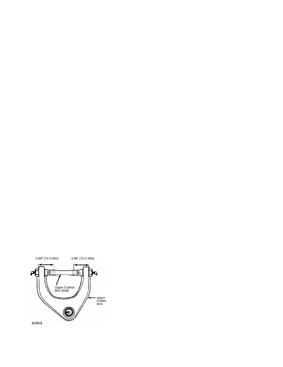
1) To install, reverse removal procedure. On Montero, ensure
control arm shaft is correctly positioned before installing. Rotate
control arm shaft to obtain correct measurement. See Fig. 6.
Fig. 6: Positioning Upper Control Arm Shaft (Montero)
Courtesy of Mitsubishi Motor Sales of America.
2) On Ram-50 & Pickup, install control arm-to-crossmember
bolts from the inside of crossmember, with nuts against control arm
shaft.
3) On Montero, install control arm-to-crossmember bolts from
the outside of control arm, with nuts against crossmember.
4) Ensure alignment shims are placed in original location.
When installing shock absorber, ensure White paint mark on lower end
of shock faces toward the outside of vehicle. Tighten shock absorber
upper nut until distance from end of threads to nut is .27-.31" (7-8
mm). Install shock lock nut.
5) Tighten bolts to specification. See TORQUE SPECIFICATIONS
table at end of article. Bleed brakes. Adjust anchor bolt to proper
torsion bar setting. See TORSION BAR under REMOVAL & INSTALLATION.
Check wheel alignment and adjust if necessary.
WHEEL BEARINGS R & I
REMOVAL
1) Raise and support vehicle. Remove wheel assembly. Remove
caliper assembly. Remove locking hub. See LOCKING HUB under REMOVAL &
INSTALLATION.
2) Remove lock washer. Using Socket (MB990954), remove lock
nut. Remove front hub assembly from steering knuckle.
3) Remove oil seal and bearings from hub. If bearing races
need to be replaced, drive bearing races from hub using brass drift
and hammer.
INSTALLATION
1) Before installing, lubricate outside surfaces of bearing
outer races with grease. Install bearing outer races in hub. Ensure
bearing races are fully seated.
2) Pack bearings with grease. Install inner bearing in hub.
On Montero, install seal in hub using Seal Installer (MB990955). On
Pickup, use Seal Installer (MB990985).
3) Install seal until seal is even with hub surface. To
complete installation, reverse removal procedure. Adjust wheel
bearings. See WHEEL BEARINGS under ADJUSTMENTS & INSPECTION. Tighten
bolts to specification. See TORQUE SPECIFICATIONS table.
TORQUE SPECIFICATIONS
TORQUE SPECIFICATIONS TABLE
Application Ft. Lbs. (N.m)
Anchor Bolt Lock Nut . . . . 29-36 (39-49)
Automatic Hub Cover . . . .. 13-25 (18-34)
Ball Joint Nut
Lower . . . . . ... 87-130 (118-176)
Upper . . . . . . .. 43-65 (58-88)
Ball Joint-to-Lower
Control Arm Bolt . . . ... 39-54 (53-73)
Caliper Bolt . . . . . . 58-72 (79-98)
Control Arm-to-Frame Bolt
Lower . . . . . (1) 101-116 (137-157)
Upper . . . . . . . 72-87 (98-118)
Locking Hub-to-Hub/Rotor Bolt . 36-43 (49-58)
Manual Hub Cover Bolt . . . . .. 10 (14)
Shock Absorber Lower Mount Bolt
Montero . . . . . . 11-16 (15-22)
Ram-50 & Pickup . . . . . .. 10 (14)
Shock Absorber Shaft Nut . . . 10-13 (14-18)
Tie Rod Nut . . . . . . . 33 (45)
Torque Arm Bolt . . . . . 69-87 (94-118)
INCH Lbs. (N.m)
Stabilizer Bar Clamp Bolt . . 84-108 (8-12)
(1) - Tighten with vehicle at normal operating
height.
Нет комментариевНе стесняйтесь поделиться с нами вашим ценным мнением.
Текст