Mitsubishi Montero (1991+). Manual — part 193
4) If control arm bushing needs replacing, use press and
Bushing Remover/Installer (MB990883-01). Press bushing from control
arm. See Fig. 4.
5) Coat bushing and control arm with soapy solution. Using
press and bushing remover/installer, press bushing into control arm.
Position bushing so there is equal distance from bushing-to-control
arm at both ends.
6) Reverse bushing remover/installer to install bushing.
Position bushing so there is equal distance from bushing-to-control
arm at both ends.
CAUTION: Tighten lower control arm shaft and pivot bolt to
specification with vehicle at normal operating height.
INSTALLATION
1) To install, reverse removal procedure. Ensure White mark,
located on lower mounting end of shock absorber, faces toward outside
of vehicle. Tighten lower control arm shaft and pivot bolt to
specification with vehicle at normal operating height.
2) Tighten bolts to specification. See TORQUE SPECIFICATIONS
table at end of article. Install new nut on stabilizer bar-to-control
arm bolt. Tighten stabilizer bar-to-control arm bolt until distance
from threaded end of bolt to nut is .24-.31" (6.0-7.8 mm).
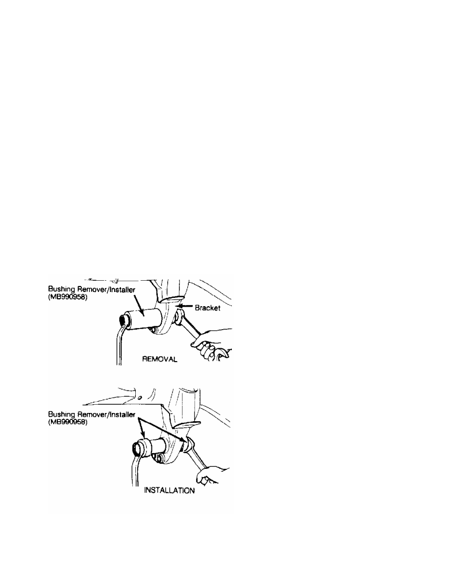
Fig. 3: Replacing Bracket Bushing
Courtesy of Mitsubishi Motor Sales of America.
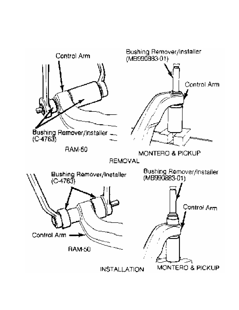
Fig. 4: Replacing Lower Control Arm Bushing
Courtesy of Mitsubishi Motor Sales of America.
STABILIZER BAR R & I
REMOVAL
Remove skid plate (if equipped). Remove stabilizer bar bolt
from lower control arm. Remove stabilizer bar clamp-to-hanger bolts.
Remove stabilizer bar and bushings. Remove stabilizer bar-to-frame
hangers (if necessary).
INSTALLATION
Inspect bushings for wear. Check stabilizer bar for
deformation. To install, reverse removal procedure. Install stabilizer
bar-to-frame hangers and stabilizer bar-to-control arm bolt using new
nuts. Tighten hanger-to-frame nut and stabilizer bar-to-control arm
nut until distance from threaded end of bolt to nut is .24-.32" (6.1-
8.1 mm).
STEERING KNUCKLE R & I
REMOVAL
1) Raise and support vehicle. Remove wheel assembly. Remove
brake caliper. Remove hub/rotor assembly. See WHEEL BEARINGS under
REMOVAL & INSTALLATION. Remove dust cover from steering knuckle.
2) Disconnect tie rod end from steering knuckle. Loosen
torsion bar anchor arm assembly adjusting nut. Loosen ball joint-to-
steering knuckle nuts. Using ball joint separator, separate ball
joints from steering knuckle.
3) Detach upper and lower ball joints from steering knuckle.
Remove steering knuckle from drive axle. Remove oil seal and spacer
from steering knuckle.
INSPECTION
Inspect steering knuckle for cracks. Inspect spindle and
steering knuckle needle bearing for wear or damage.
INSTALLATION
1) If needle bearing requires replacement, drive bearing from
steering knuckle. Use Bearing Driver (MB990956-01) and Handle
(MB9909938-01) to install needle bearing.
NOTE: DO NOT reuse steering knuckle bearing if removed.
2) Using bearing installer and handle, install new needle
bearing until bearing is even with steering knuckle end face. Apply
SAE J310 NLGI No. 2 grease to bearing roller surface and spacer-to-
steering knuckle contact areas. Install spacer with chamfered side
toward inside of vehicle.
3) Using Seal Installer (MB990985-01) and Handle (MB990938-
01), install seal in steering knuckle until seal is even with steering
knuckle end face. Apply grease to seal lip area and inside of seal. To
complete installation, reverse removal procedure. Tighten bolts to
specification. See TORQUE SPECIFICATIONS table at end of article.
TORSION BAR R & I
CAUTION: Mark torsion bar and anchor arm location for reassembly
reference before removing.
REMOVAL
1) Raise and support vehicle. Support lower control arm with
jack stand. Loosen anchor arm adjusting bolt lock nut. On Montero,
remove heat protector from frame (right side only). Loosen anchor bolt
to release torsion bar tension.
2) Place reference marks on front of torsion bar, torque arm
and torsion bar-to-torque arm for reassembly reference. Remove anchor
arm. See Fig. 1.
3) Remove dust cover from end of torsion bar. On Montero,
remove heat cover (left side only) located between dust cover and
torsion bar. On all models, remove torsion bar.
INSPECTION
Inspect all splined areas for damage. Inspect dust covers for
cracks or damage. Check for bent anchor bolts. Replace components as
necessary.
INSTALLATION
1) Apply grease to splined areas of torsion bar, anchor arm,
torque arm splines, anchor bolt threads and inside of dust cover.
Check for left and right identification marks on torsion bars’ ends.
Ensure torsion bars are installed in correct location.
2) Install torsion bar in torque arm, with identification
mark toward front of vehicle. Align mark on torque arm with mating
mark on torsion bar. When installing a new torsion bar, align the
White paint spline with index mark on front torque arm.
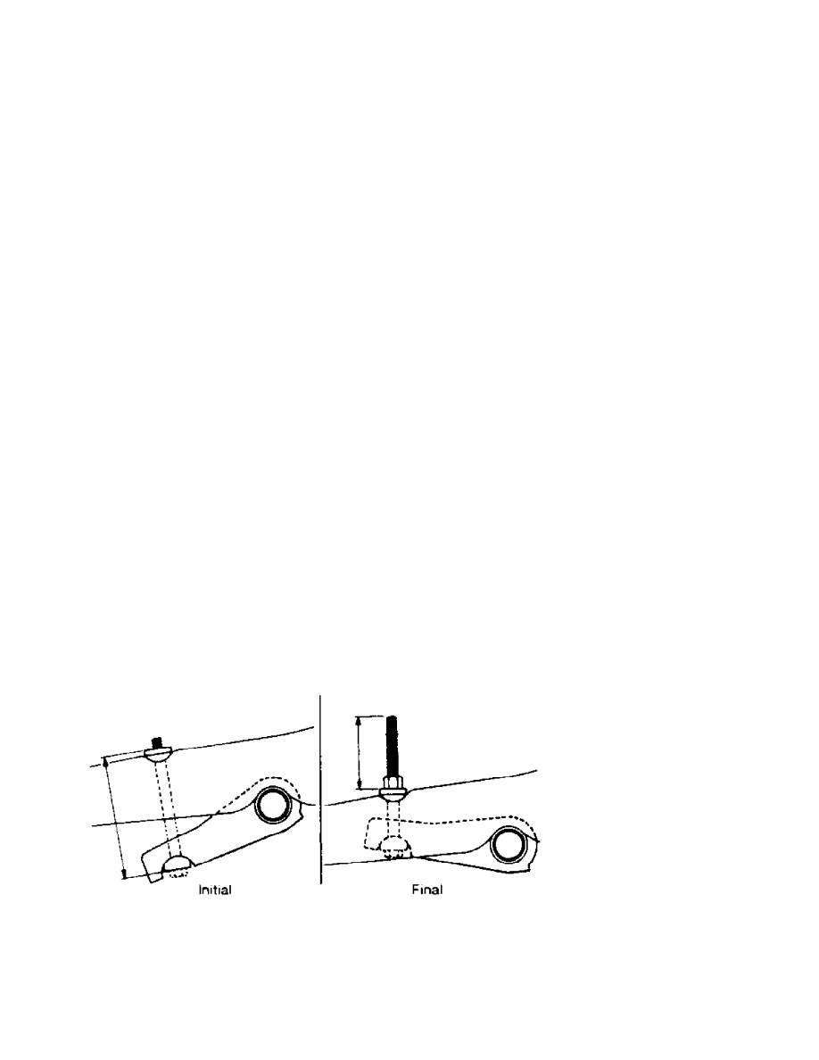
3) Install anchor arm on torsion bar so initial length of
adjusting bolt from flat surface of upper and lower half moon washers
is within specification. See Fig. 5.
4) See ANCHOR BOLT INITIAL SPECIFICATIONS table. Ensure upper
control arm rebound stopper is contacting crossmember before adjusting
initial setting.
NOTE: Ensure upper control arm rebound stopper is contacting
crossmember when adjusting initial settings.
Fig. 5: Adjusting Anchor Arm Bolt
Courtesy of Mitsubishi Motor Sales of America.
ANCHOR BOLT INITIAL SPECIFICATIONS TABLE
Нет комментариевНе стесняйтесь поделиться с нами вашим ценным мнением.
Текст