Mitsubishi Montero (1991+). Manual — part 322

PFI VIN [3]. It is a perfect example of the peak and hold theory. The
waveform shows a 1-amp per division current flow, ramping to 4 amps
and then decreasing to 1-amp to hold the injector open.
Fig. 13: Injector Bank w/Normal Current Flow - Current Pattern
EXAMPLE #6 - CURRENT CONTROLLED DRIVER
This next known-good waveform is from a Ford 5.0L V8 CFI VIN
[F]. See Fig. 14. The pattern, which is set on a 250 milliamps scale,
indicates a 1.25 amp peak draw and a hold at 350 milliamps.
Fig. 14: Single Injector w/Normal Current Flow - Current Pattern
EXAMPLE #7 - CURRENT CONTROLLED DRIVER
The known-good current controlled type waveform in Fig. 15 is
from a GM 2.0L TBI VIN [1]. With the lab scope set at 2 amps per
division, notice that this system peaks at 4 amps and holds at 1 amp.
The next waveform is from the same type of engine, except

that it shows a faulty injector. See Fig. 16. Notice that the current
went to almost 5 amps and stayed at 1 amp during the hold pattern.
Excessive amounts of current flow from bad injectors are a common
source of intermittent computer shutdown. Using a current waveform
pattern is the most accurate method of pinpointing this problem.
Fig. 15: Single Injector w/Normal Current Flow - Current Pattern
Fig. 16: Single Injector w/Excessive Current Flow - Current Pattern
EXAMPLE #8 - CURRENT CONTROLLED DRIVER
This known-good CPI system waveform from a GM 4.3L V6 CPI VIN
[W] peaks at 4 amps and holds at 1-amp. See Fig. 17 for waveform.
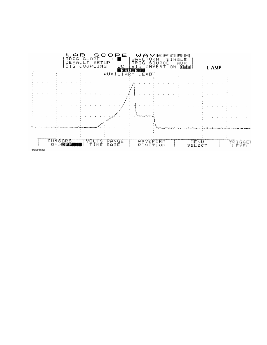
Fig. 17: Single Injector w/Normal Current Flow - Current Pattern
VOLTAGE WAVEFORM SAMPLES
EXAMPLE #1 - VOLTAGE CONTROLLED DRIVER
These two known-good waveform patterns are from a Ford 4.6L
V8 VIN [W]. Fig. 18 illustrates the 64 volt inductive kick on this
engine, indicating no clamping is occurring. The second pattern,
Fig. 19, was taken during hot idle, closed loop, and no load.

Fig. 18: Injector Bank - Known Good - Voltage Pattern
Нет комментариевНе стесняйтесь поделиться с нами вашим ценным мнением.
Текст