Mitsubishi Montero (1991+). Manual — part 188
CAUTION: Perform tests in less than 10 seconds to prevent coil
damage.
1) Disconnect field coil wire from terminal "M" at starter
solenoid. See Fig. 2. Connect jumper wire between positive battery
terminal of 12-volt battery and terminal "S" of starter solenoid.
2) Connect a second jumper wire from negative battery
terminal and touch starter case. If solenoid plunger is pulled-in,
hold-in coil is good. If not, replace solenoid.
RETURN TEST
CAUTION: Perform tests in less than 10 seconds to prevent coil
damage.
1) Disconnect field coil wire from terminal "M" at starter
solenoid. See Fig. 2. Connect jumper wire between positive battery
terminal of 12-volt battery and terminal "M" of starter solenoid.
2) Connect a second jumper wire from negative battery
terminal and touch starter case. Pull pinion outward and release it.
Replace solenoid if pinion remains outward.
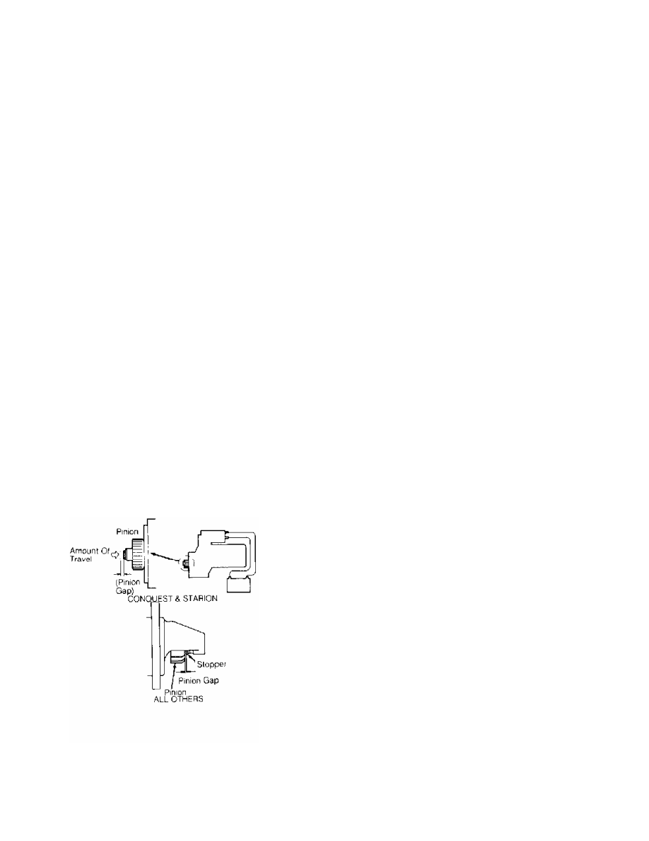
PINION GAP CHECK
1) Disconnect field coil wire from terminal "M" at starter
solenoid. See Fig. 2. Connect jumper wire between positive battery
terminal of 12-volt battery and terminal "S" of starter solenoid.
2) Connect a second jumper wire from negative battery
terminal and touch terminal "M" of starter solenoid. See Fig. 2.
Measure clearance between pinion and stopper. See Fig. 3.
3) Clearance should be within specification. See STARTER
SPECIFICATIONS table. Adjust clearance by adding or removing gaskets
between solenoid and front housing.
Fig. 3: Measuring Pinion Gap
Courtesy of Mitsubishi Motor Sales of America.
REMOVAL & INSTALLATION
Remove negative battery cable. If necessary, raise vehicle on
hoist. Remove starter mounting bolts and starter. To install, reverse
removal procedure.
NOTE: On Raider models with A/T, it may be necessary to disconnect
transmission oil cooler line for starter removal.
OVERHAUL
Check commutator for out-of-round and proper amount of
undercut. Replace or repair armature if not within specification. See
STARTER SPECIFICATIONS table. Ensure brushes are not worn beyond wear
line (outer line closest to commutator contact surface). Check pinion
gap. See PINION GAP CHECK in this article.
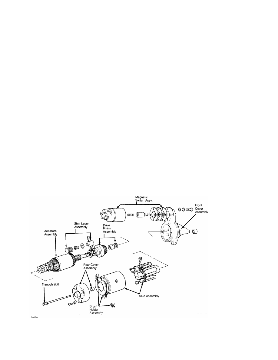
DISASSEMBLY
NOTE: Procedures may vary slightly between conventional and
reduction gear starters.
1) Loosen nut securing connecting plate-to-magnetic switch
"M" terminal. Remove screws securing magnetic switch and remove switch
(solenoid) assembly. Remove through bolts and brush cover assembly.
Tap yoke assembly loose with wooden mallet. Remove yoke, armature
assembly and pinion shift lever.
2) Remove pinion stop ring from end of armature shaft by
pushing stop ring to clutch side. Remove snap ring and overrunning
clutch assembly from armature shaft.
Fig. 4: Disassembled View of Typical Mitsubishi Starter
CLEANING & INSPECTION
Clean all parts. Do not use grease dissolving solvent on
overrunning clutch, armature assembly, solenoid assembly or field
coils due to possible damage. Inspect all parts for damage or wear and
replace as required.
BENCH TESTS
Brushes & Springs
Check brush spring tension using a spring scale. Check brush
contact surface condition and brush length. Check lead clip and wire
connections and condition of brush holders. Replace as required. See
Brush Spring Tension and Minimum Brush Length Charts.
BRUSH & SPRING SPECIFICATIONS
BRUSH SPRING TENSION
Application Ozs. (g)
Chrysler Corp. Imports . . . 46-59 (1302-1670)
MINIMUM BRUSH LENGTH (1)
Application In. (mm)
Chrysler Corp. Imports . . . . ... .45 (11.5)
(1) - Minimum brush length should coincide with the
brush wear mark.
Armature
Check external condition of armature for scoring or other
damage. Measure shaft distortion with dial indicator. Replace armature
if shaft distortion exceeds .004" (.10 mm).
Commutator
1) Inspect commutator for roughness, grooves, burns or
pitting. Sand lightly with 500 grit sandpaper if necessary. Check
commutator for out-of-round and mica insulators undercut to a depth of
.020-.031" (.5-.8 mm).
2) If necessary, commutator may be turned less than .04" (1
mm) from original size and mica undercut. Replace if excessively worn.
Field Coil
1) Check field coil continuity by connecting test probe of
circuit tester or an ohmmeter to the field coil positive terminal and
brush holder. If circuit is open, replace field coil.
2) Check for grounding of field coils by placing one probe of
circuit tester on starter housing and other probe to field coil
positive terminal. If little or no resistance, field coil is grounded
and must be replaced.
Overrunning Clutch Assembly
1) Inspect pinion assembly and sleeve. Sleeve should slide
freely on armature shaft and spline. If damage or resistance is noted,
replace assembly.
2) Check pinion and flywheel teeth for excessive rubbing or
damaged teeth. Replace as required.
Pinion Gear Clearance
The clearance between the pinion gear and pinion stopper
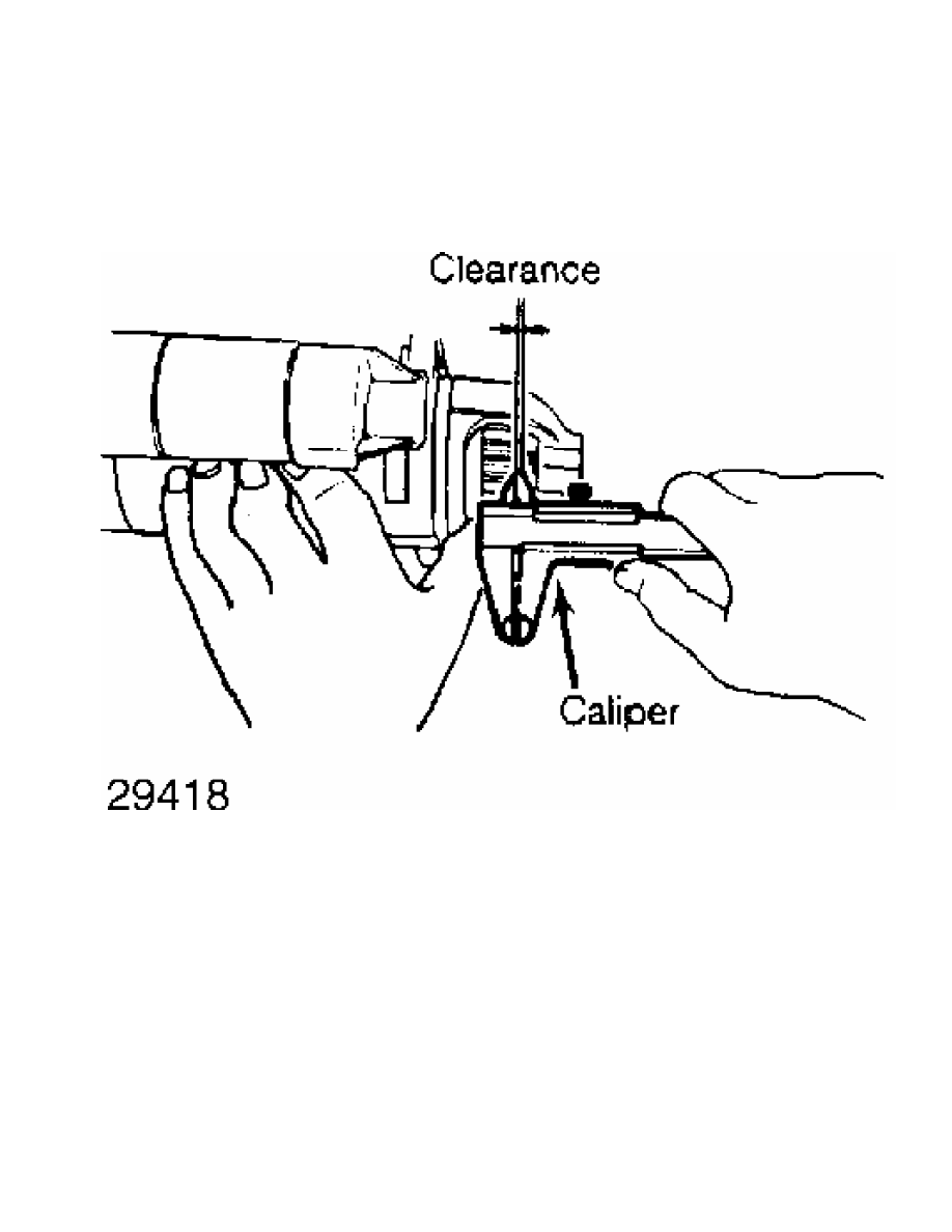
collar should be .02-.08" (.51-2.03 mm) on Mitsubishi starters, when
solenoid is engaged. Adjust as necessary by changing shims between
solenoid and starter yoke.
Fig. 5: Measuring Pinion Gear-to-Pinion Stopper Clearance
Pinion Case Bearing
Inspect bearing for wear and check side play. If clearance
exceeds .008" (.2 mm), replace bearing. New bearing clearance should
be .002-.004" (.05-.10 mm) for Mitsubishi starters.
NOTE: Ensure that bearing is installed so that end of bearing is
flush with gear case end.
REASSEMBLY
To reassemble, reverse disassembly procedure. Fill gear case
on reduction gear models with grease. Lightly oil pinion and all
bearing surfaces.
Нет комментариевНе стесняйтесь поделиться с нами вашим ценным мнением.
Текст