Mitsubishi Montero (1991+). Manual — part 291
Disassembly
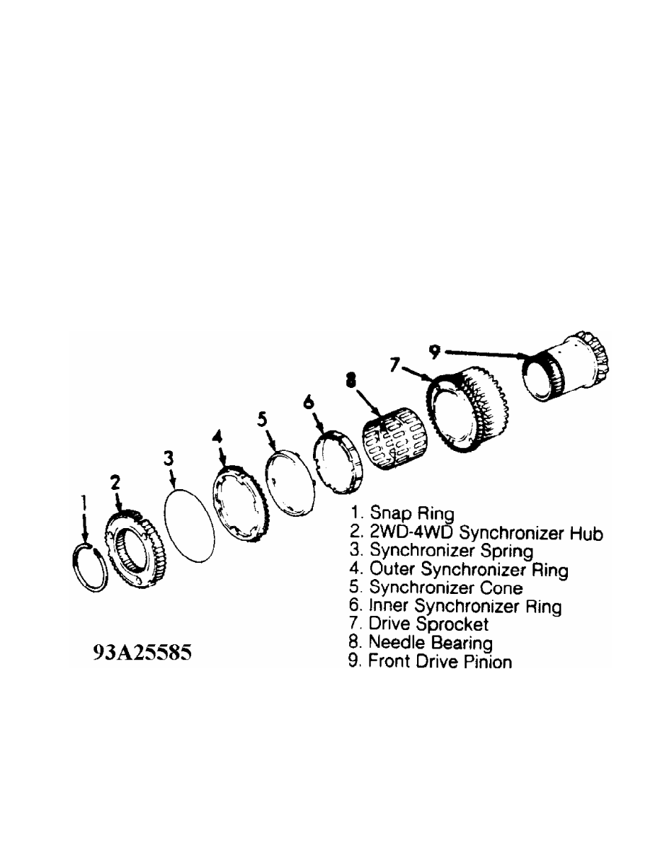
Remove snap ring, 2WD-4WD synchronizer hub and synchronizer
spring. Remove outer synchronizer ring, synchronizer cone and inner
synchronizer ring. Remove drive sprocket and needle bearing from front
drive pinion. Inspect inner and outer synchronizer rings and cone for
excessive wear. Install inner and outer synchronizer rings and cone
onto drive sprocket. Measure distance between drive sprocket and outer
synchronizer. If distance is less than .0118" (.300 mm) replace
synchronizer parts as a set.
Reassembly
Install drive sprocket and needle bearing onto front drive
pinion. Apply transfer case gear oil to contacting surfaces of inner
and outer synchronizer rings and synchronizer cone. Install inner and
outer synchronizer rings and synchronizer cone. Install synchronizer
spring, 2WD-4WD synchronizer hub and snap ring to complete assembly.
When installing new snap ring, select thickest ring that will fit into
groove. Acceptable snap ring clearance is 0-.003" (0-.080 mm).
Fig. 8: Exploded View Of 2WD-4WD Synchronizer (Montero)
Courtesy of Mitsubishi Motor Sales of America.
TRANSFER CASE REASSEMBLY
NOTE: ALWAYS replace all gaskets, oil seals, snap rings and spring
pins with new parts. Coat both sides of gaskets and bolt
threads with sealant. Lubricate all sliding and rotating
parts with transfer case gear oil before assembling.
Reassembly (Ram-50)
1) Install input gear and front output shaft oil seals into
transfer case housing. Pack grease between lips of seals and press
seal circumference uniformly.
2) Install input gear assembly in transfer case. See Figs. 3
and 6. Input gear assembly snap ring is available in selective
thicknesses. Use thickest snap ring that will fit into input shaft
groove. Allowed snap ring clearance is 0-.0024" (0-.060 mm).
3) Insert needle bearing onto rear output shaft assembly.
Install high-low synchronizer sleeve and shift fork. Install 2WD-4WD
shift fork. Engage chain securely on front and rear output shaft
sprockets. Assemble 2WD-4WD synchronizer sleeve with 2WD-4WD shift
fork. Install assembly over 2WD-4WD shift rail. Install front and rear
output shafts with chain as an assembly.
4) Install 2WD-4WD shift lug, distance piece, 2WD-4WD shift
rail and spring pin. Ensure slit in spring pin is in line with 2WD-4WD
shift rail. Install 2 spring retainers with spring on 2WD-4WD shift
rail. Install snap ring to end of 2WD-4WD shift rail. See Fig. 3.
5) Insert 2 needle bearings and spacer into countergear.
Install one thrust washer at each end of countergear. Ensure tab on
thrust washers fits into groove of transfer case. Install countergear
shaft assembly with "O" ring.
6) Install side cover and gasket. Install oil guide. Apply
sealant to both sides of gasket and install gasket and chain cover.
Ensure oil guide end fits into chain cover opening. Fit snap ring into
groove of rear bearing on rear output shaft. Tighten bolts to
specification. See TORQUE SPECIFICATIONS.
7) Install interlock plunger. Shift 2WD-4WD shift rail to 4WD
position. Install high-low shift rail through high-low shift fork in
case. Install 2 poppet balls and springs. Install seal plugs. When
installing poppet springs, smaller end must be toward ball.
8) On models with pulse generator, install pulse rotor, wave
spring and spacer. Measure protrusion "A" of front output shaft rear
bearing and recess "B" of cover and calculate clearance. See Fig. 9.
If clearance is greater than .079" (2.0 mm), select and install spacer
to bring clearance within specification. If clearance is less than .
079" (2.0 mm), use wave spring alone. Apply sealant to both sides of
gasket and install gasket and cover. Install pulse generator (if
equipped).
9) On all models, align high-low shift fork and shift rail
spring holes and drive in roll pin with punch. Roll pin should be
installed with slit on center line of shift rail. Install wave spring
on rear of rear output shaft bearing. Apply sealant to both sides of
rear cover gasket. Install gasket and cover.
10) Check output shaft end play. Measure protrusion "A" of
rear output shaft rear bearing and recess "B" of cover and calculate
clearance. Ensure end play is 0-.004" (0-.10 mm). Apply sealant to
both sides of gasket and install gasket and cover. See Fig. 9.
11) Install speedometer sleeve assembly in rear cover. Align
match mark on speedometer sleeve assembly in rear cover. See Fig. 10.
Align match mark on speedometer sleeve with mark on case according to
number of teeth on speedometer driven gear. Install speedometer driven
gear sleeve clamp and tighten bolt to specification. Install both 4WD
indicator light switches with steel balls. See TORQUE SPECIFICATIONS.
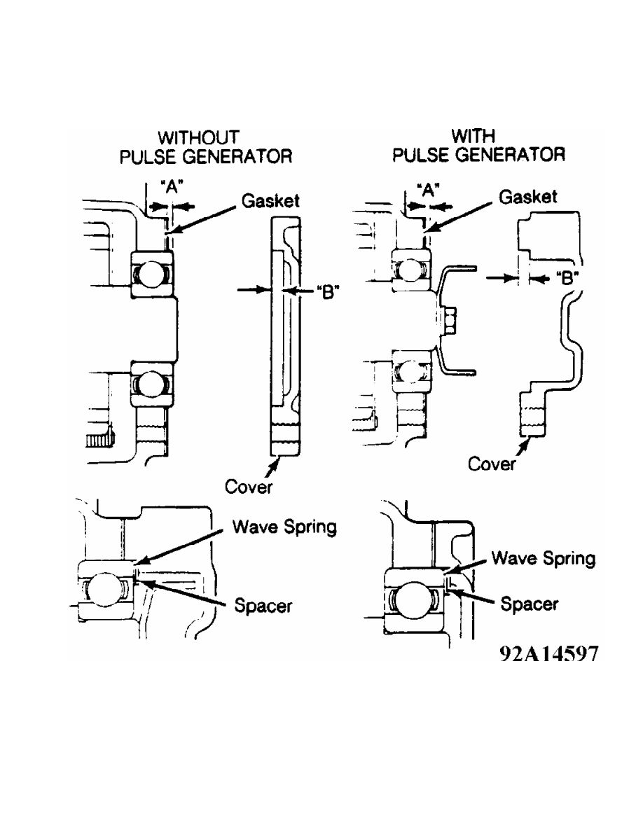
Fig. 9: Measuring Rear Output Shaft Bearing Clearance (Ram-50)
Courtesy of Mitsubishi Motor Sales of America.
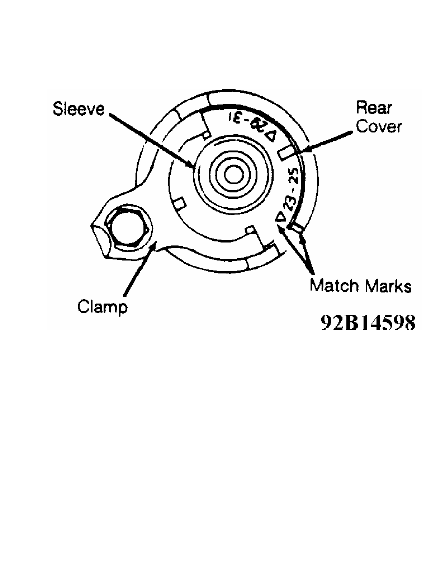
Fig. 10: Aligning Speedometer Sleeve
Courtesy of Mitsubishi Motor Sales of America.
Reassembly (Montero)
1) Install input gear and front output shaft oil seals into
transfer case housing. Install transfer input gear assembly baffle
plate and input gear seal. Pack grease between lips of seals and press
seal circumference uniformly.
2) Install 2WD-4WD shift lug into transfer case. Install
spring retainer and spring to shift rail and install into shift lug.
Press on shift rail to align spring pin holes in shift rail and shift
lug. While holding shift rail, tap spring pin into place with slit
facing center of shift rail.
3) Install transfer input gear assembly and snap ring. Select
thickest snap ring that will fit into groove. Allowed snap ring
clearance is 0-.0024" (0-.060 mm). Insert needle bearing onto transfer
drive shaft assembly. Install high-low synchronizer sleeve and shift
fork assembly. Install transfer drive shaft assembly.
4) Install transfer countergear shaft thrust washers, needle
bearings, bearing spacer and transfer countergear. Install one thrust
washer at each end of transfer countergear. Ensure tab on thrust
washers fits into groove of transfer case. Install counter gear shaft
from transmission case side so lock plate groove is aligned with lock
plate. Install lock plate. Install side cover and gasket.
5) Install bearing retainer. If reusing bearing retainer
bolts, apply Locking Adhesive (3M 4170 Stud Lock) to threads. Install
oil dam cover. Install differential lock hub, snap ring, steel ball
and sleeve. Select thickest snap ring that will fit into groove.
Allowed snap ring clearance is 0-.003" (0-.08 mm). Install 2WD-4WD
synchronizer sleeve, 2WD-4WD shift fork, spring, spring seat and 2WD-
Нет комментариевНе стесняйтесь поделиться с нами вашим ценным мнением.
Текст