Mitsubishi Montero (1991+). Manual — part 289

Fig. 1: 4WD Indicator Control Unit Testing (Montero)
Courtesy of Mitsubishi Motor Sales of America.
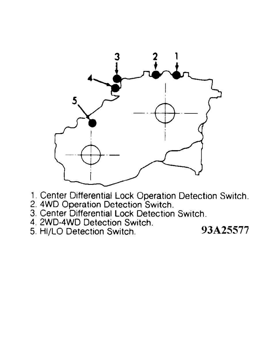
Fig. 2: Detection Switch Testing Locations (Montero)
Courtesy of Mitsubishi Motor Sales of America.
REMOVAL & INSTALLATION
Removal
1) Remove negative battery cable. Remove transfer case skid
plate (if equipped). Scribe alignment marks and remove both drive
shafts. Drain oil from transfer case. Disconnect wiring harness from
back-up light switch, all 4WD switches and any other electrical
connectors (if equipped).
2) Disconnect speedometer cable from drive. Unclip cable from
case. Place transfer case shifter in "2H" position and transmission in
Neutral. Remove 6 bolts holding control lever assembly. Remove control
lever assembly and gasket.
3) Remove select plunger bore plug at right side of case.
Remove select spring and plunger. Remove change shifter spring pin.
Remove change shifter. Remove transfer case mount. Remove 4 bolts and
2 nuts holding transfer case to adapter. Remove transfer case from
vehicle.
Installation
1) Position transmission shifter in Neutral and transfer case
lever in "2H" position. Install neutral return plungers and springs in
holes on top of adapter. Tighten plug until it is flush with adapter
surface. Cover plug threads with sealant.
2) Coat inside of change shifter with grease. Ensure change
shifter pin protrudes 1/8" above change shifter when installed. Mount
detent plunger spring and install plug (if equipped). To complete
installation, reverse removal procedure. Fill transfer case with API
GL-4 or higher 75W-90 or 75W-85W gear oil.
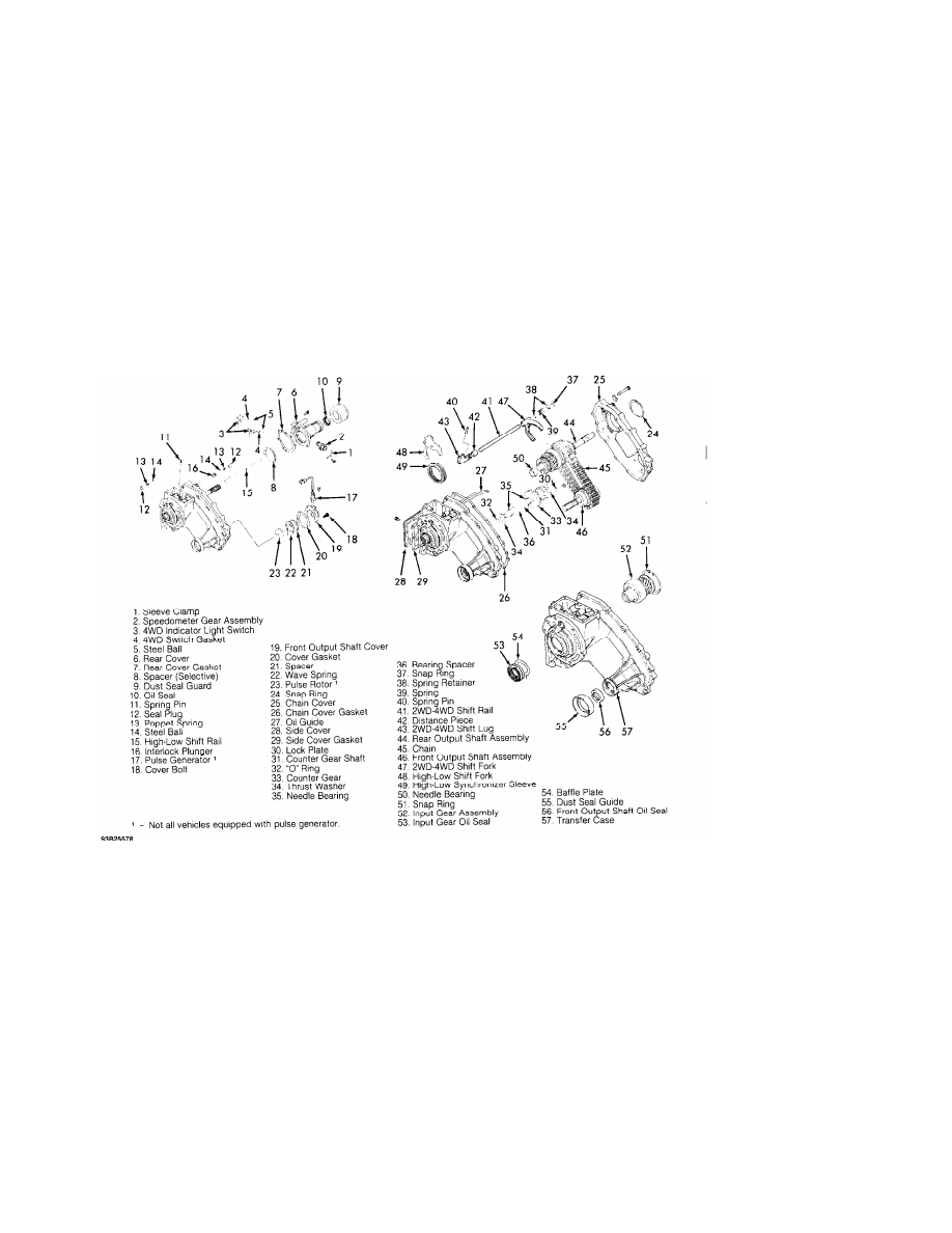
Fig. 3: Exploded View Of Transfer Case (Ram-50)
Courtesy of Mitsubishi Motor Sales of America.
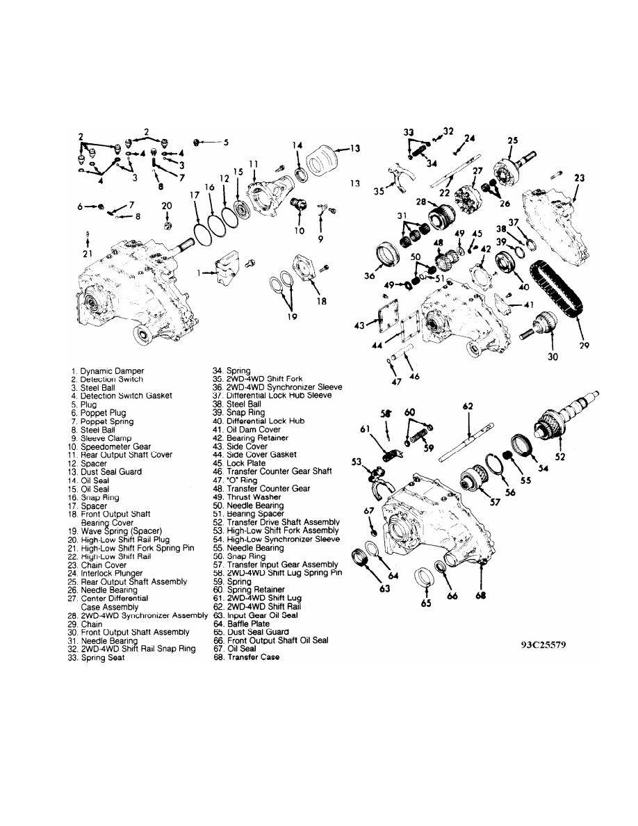
Fig. 4: Exploded View Of Transfer Case (Montero)
Courtesy of Mitsubishi Motor Sales of America.
TRANSFER CASE DISASSEMBLY
Disassembly (Ram-50)
1) Remove both 4WD indicator switches and steel balls. Remove
speedometer gear assembly. Remove output shaft cover, gasket, wave
spring and spacer. See Fig. 3. Remove rear cover, rear cover gasket
and spacer from chain cover. Drive roll pin out of high-low shift
fork.
Нет комментариевНе стесняйтесь поделиться с нами вашим ценным мнением.
Текст