Mitsubishi Montero (1991+). Manual — part 324

Fig. 23: Injector Bank - Known Good - Voltage Pattern
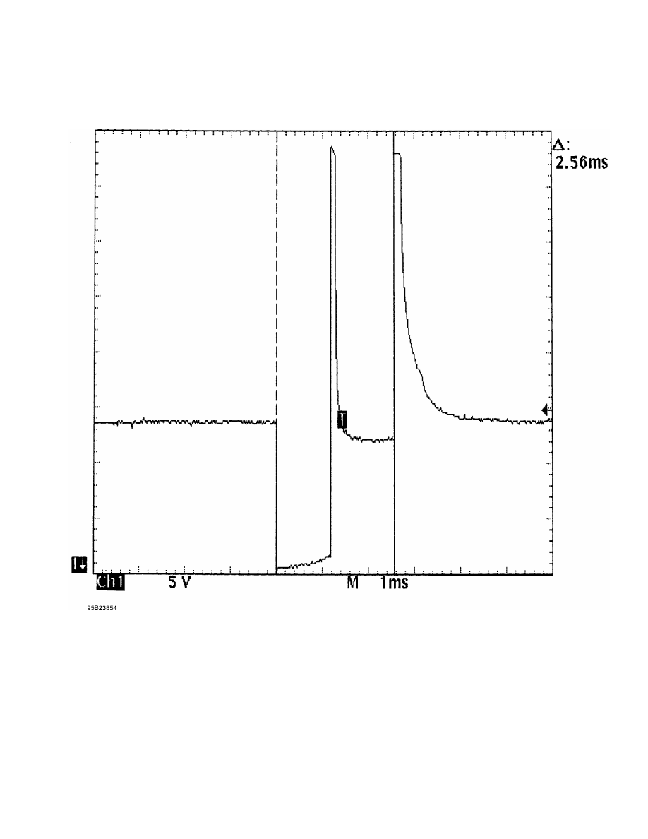
Fig. 24: Injector Bank - Known Good - Voltage Pattern
EXAMPLE #6 - CURRENT CONTROLLED DRIVER
This known-good pattern from a Ford 3.0L V6 PFI VIN [U]
illustrates that a zener diode inside the computer is used to clamp
the injector’s inductive kick to 35-volts on this system. See Fig. 25.
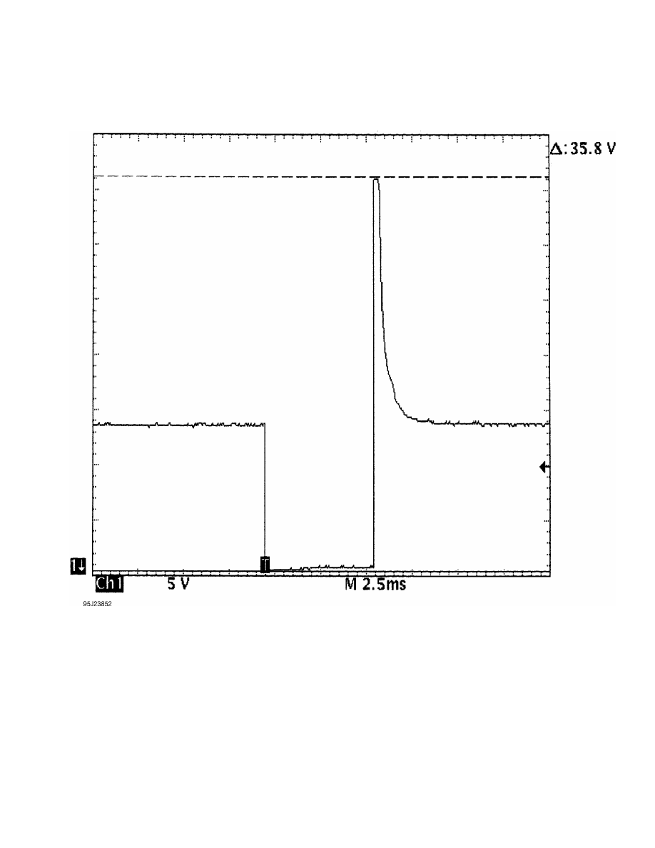
Fig. 25: Injector Bank - Known Good - Voltage Pattern
EXAMPLE #7 - CURRENT CONTROLLED DRIVER
This known-good waveform from a Ford 5.0L V8 CFI VIN [F] was
taken during hot idle, closed loop, and no load. See Fig. 26.
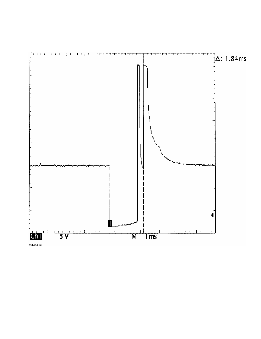
Fig. 26: Single Injector - Known Good - Voltage Pattern
EXAMPLE #8 - CURRENT CONTROLLED DRIVER
These two known-good waveform patterns are from a GM 2.0L In-
Line 4 VIN [1]. Fig. 27 illustrates the 78 volt inductive spike that
indicates a zener diode is not used. The second waveform, Fig. 28, was
taken during hot idle, closed loop, and no load.
Нет комментариевНе стесняйтесь поделиться с нами вашим ценным мнением.
Текст