Mitsubishi Montero (1991+). Manual — part 319
3800 engines were suffering from exactly this. The point is that a
lack of detail could cause misdiagnosis.
As you might have guessed, a lab scope would not miss this.
RELATIONSHIP BETWEEN DWELL & DUTY CYCLE READINGS TABLE ( 1)
Dwell Meter (2) Duty Cycle Meter
1 . . . . . . . . . . . . . 1%
15 . . . . . . . . . . . . .. 25%
30 . . . . . . . . . . . . .. 50%
45 . . . . . . . . . . . . .. 75%
60 . . . . . . . . . . . . . 100%
(1) - These are just some examples for your understanding.
It is okay to fill in the gaps.
(2) - Dwell meter on the six-cylinder scale.
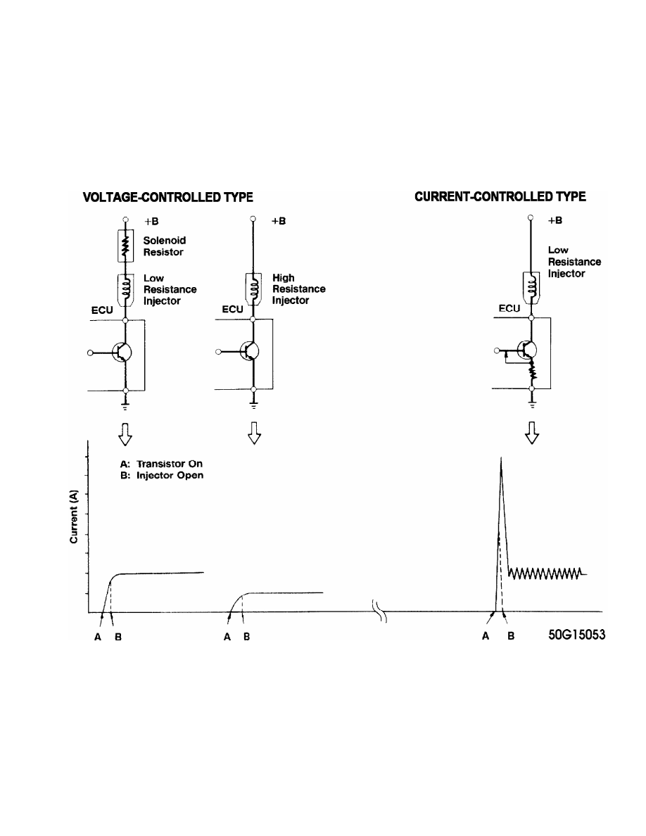
THE TWO TYPES OF INJECTOR DRIVERS
OVERVIEW
There are two types of transistor driver circuits used to
operate electric fuel injectors: voltage controlled and current
controlled. The voltage controlled type is sometimes called a
"saturated switch" driver, while the current controlled type is
sometimes known as a "peak and hold" driver.
The basic difference between the two is the total resistance
of the injector circuit. Roughly speaking, if a particular leg in an
injector circuit has total resistance of 12 or more ohms, a voltage
control driver is used. If less than 12 ohms, a current control driver
is used.
It is a question of what is going to do the job of limiting
the current flow in the injector circuit; the inherent "high"
resistance in the injector circuit, or the transistor driver. Without
some form of control, the current flow through the injector would
cause the solenoid coil to overheat and result in a damaged injector.
VOLTAGE CONTROLLED CIRCUIT ("SATURATED SWITCH")
The voltage controlled driver inside the computer operates
much like a simple switch because it does not need to worry about
limiting current flow. Recall, this driver typically requires injector
circuits with a total leg resistance of 12 or more ohms.
The driver is either ON, closing/completing the circuit
(eliminating the voltage-drop), or OFF, opening the circuit (causing a
total voltage drop).
Some manufacturers call it a "saturated switch" driver. This
is because when switched ON, the driver allows the magnetic field in
the injector to build to saturation. This is the same "saturation"
property that you are familiar with for an ignition coil.
There are two ways "high" resistance can be built into an
injector circuit to limit current flow. One method uses an external
solenoid resistor and a low resistance injector, while the other uses
a high resistance injector without the solenoid resistor. See the left
side of Fig. 1.
In terms of injection opening time, the external resistor
voltage controlled circuit is somewhat faster than the voltage
controlled high resistance injector circuit. The trend, however, seems
to be moving toward use of this latter type of circuit due to its
lower cost and reliability. The ECU can compensate for slower opening
times by increasing injector pulse width accordingly.
NOTE: Never apply battery voltage directly across a low resistance
injector. This will cause injector damage from solenoid coil
overheating.
Fig. 1: Injector Driver Types - Current and Voltage
CURRENT CONTROLLED CIRCUIT ("PEAK & HOLD")
The current controlled driver inside the computer is more
complex than a voltage controlled driver because as the name implies,
it has to limit current flow in addition to its ON-OFF switching
function. Recall, this driver typically requires injector circuits
with a total leg resistance of less than 12 ohms.
Once the driver is turned ON, it will not limit current flow
until enough time has passed for the injector pintle to open. This
period is preset by the particular manufacturer/system based on the
amount of current flow needed to open their injector. This is
typically between two and six amps. Some manufacturers refer to this
as the "peak" time, referring to the fact that current flow is allowed
to "peak" (to open the injector).
Once the injector pintle is open, the amp flow is
considerably reduced for the rest of the pulse duration to protect the
injector from overheating. This is okay because very little amperage
is needed to hold the injector open, typically in the area of one amp
or less. Some manufacturers refer to this as the "hold" time, meaning
that just enough current is allowed through the circuit to "hold" the
already-open injector open.
There are a couple methods of reducing the current. The most
common trims back the available voltage for the circuit, similar to
turning down a light at home with a dimmer.
The other method involves repeatedly cycling the circuit ON-
OFF. It does this so fast that the magnetic field never collapses and
the pintle stays open, but the current is still significantly reduced.
See the right side of Fig. 1 for an illustration.
The advantage to the current controlled driver circuit is the
short time period from when the driver transistor goes ON to when the
injector actually opens. This is a function of the speed with which
current flow reaches its peak due to the low circuit resistance. Also,
the injector closes faster when the driver turns OFF because of the
lower holding current.
NOTE: Never apply battery voltage directly across a low resistance
injector. This will cause injector damage from solenoid coil
overheating.
THE TWO WAYS INJECTOR CIRCUITS ARE WIRED
Like other circuits, injector circuits can be wired in one of
two fundamental directions. The first method is to steadily power the
injectors and have the computer driver switch the ground side of the
circuit. Conversely, the injectors can be steadily grounded while the
driver switches the power side of the circuit.
There is no performance benefit to either method. Voltage
controlled and current controlled drivers have been successfully
implemented both ways.
However, 95% percent of the systems are wired so the driver
controls the ground side of the circuit. Only a handful of systems use
the drivers on the power side of the circuit. Some examples of the
latter are the 1970’s Cadillac EFI system, early Jeep 4.0 EFI (Renix
system), and Chrysler 1984-87 TBI.
INTERPRETING INJECTOR WAVEFORMS
INTERPRETING A VOLTAGE CONTROLLED PATTERN
NOTE: Voltage controlled drivers are also known as "Saturated
Switch" drivers. They typically require injector circuits
with a total leg resistance of 12 ohms or more.
NOTE: This example is based on a constant power/switched ground
circuit.
* See Fig. 2 for pattern that the following text describes.
Point "A" is where system voltage is supplied to the
injector. A good hot run voltage is usually 13.5 or more volts. This
point, commonly known as open circuit voltage, is critical because the
injector will not get sufficient current saturation if there is a
voltage shortfall. To obtain a good look at this precise point, you
will need to shift your Lab Scope to five volts per division.
You will find that some systems have slight voltage
fluctuations here. This can occur if the injector feed wire is also
used to power up other cycling components, like the ignition coil(s).
Slight voltage fluctuations are normal and are no reason for concern.
Major voltage fluctuations are a different story, however. Major
voltage shifts on the injector feed line will create injector
performance problems. Look for excessive resistance problems in the
feed circuit if you see big shifts and repair as necessary.
Note that circuits with external injector resistors will not
be any different because the resistor does not affect open circuit
voltage.
Point "B" is where the driver completes the circuit to
ground. This point of the waveform should be a clean square point
straight down with no rounded edges. It is during this period that
current saturation of the injector windings is taking place and the
driver is heavily stressed. Weak drivers will distort this vertical
line.
Point "C" represents the voltage drop across the injector
windings. Point "C" should come very close to the ground reference
point, but not quite touch. This is because the driver has a small
amount of inherent resistance. Any significant offset from ground is
an indication of a resistance problem on the ground circuit that needs
repaired. You might miss this fault if you do not use the negative
battery post for your Lab Scope hook-up, so it is HIGHLY recommended
that you use the battery as your hook-up.
The points between "B" and "D" represent the time in
milliseconds that the injector is being energized or held open. This
line at Point "C" should remain flat. Any distortion or upward bend
indicates a ground problem, short problem, or a weak driver. Alert
readers will catch that this is exactly opposite of the current
controlled type drivers (explained in the next section), because they
bend upwards at this point.
How come the difference? Because of the total circuit
resistance. Voltage controlled driver circuits have a high resistance
of 12+ ohms that slows the building of the magnetic field in the
injector. Hence, no counter voltage is built up and the line remains
flat.
On the other hand, the current controlled driver circuit has
low resistance which allows for a rapid magnetic field build-up. This
causes a slight inductive rise (created by the effects of counter
voltage) and hence, the upward bend. You should not see that here with
voltage controlled circuits.
Point "D" represents the electrical condition of the injector
windings. The height of this voltage spike (inductive kick) is
proportional to the number of windings and the current flow through
them. The more current flow and greater number of windings, the more
potential for a greater inductive kick. The opposite is also true. The
less current flow or fewer windings means less inductive kick.
Typically you should see a minimum 35 volts at the top of Point "D".
If you do see approximately 35 volts, it is because a zener
diode is used with the driver to clamp the voltage. Make sure the
beginning top of the spike is squared off, indicating the zener dumped
the remainder of the spike. If it is not squared, that indicates the
spike is not strong enough to make the zener fully dump, meaning the
injector has a weak winding.
If a zener diode is not used in the computer, the spike from
a good injector will be 60 or more volts.
Point "E" brings us to a very interesting section. As you
can see, the voltage dissipates back to supply value after the peak of
the inductive kick. Notice the slight hump? This is actually the
mechanical injector pintle closing. Recall that moving an iron core
through a magnetic field will create a voltage surge. The pintle is
Нет комментариевНе стесняйтесь поделиться с нами вашим ценным мнением.
Текст