Mitsubishi Eclipse / Eclipse Spyder (2000-2002). Service and repair manual — part 175
MULTIPORT FUEL INJECTION (MFI) DIAGNOSIS
TSB Revision
MULTIPORT FUEL INJECTION (MFI) <2.4L ENGINE>
13A-399
DIAGNOSIS
STEP 1. Check the evaporative emission purge solenoid
Refer to GROUP 17, Emission Control System
−
Evaporative
Emission Purge Solenoid Check (
Q: Is the evaporative emission purge solenoid normal?
YES : Go to Step 2.
NO : Repair or replace. Then confirm that the malfunction
symptom is eliminated.
STEP 2. Check the evaporative emission ventilation
solenoid.
Refer to GROUP 17, Emission Control System
−
Evaporative
Emission Ventilation Solenoid Check (
Q: Is the evaporative emission ventilation solenoid
normal?
YES : Check the following items, and repair or replace the
defective items.
a. Check for leaks from the vapor line or
evaporative emission canister.
b. Check for leaks from the fuel tank.
Then confirm that the malfunction symptom is
eliminated.
NO : Repair or replace. Then confirm that the malfunction
symptom is eliminated.
MULTIPORT FUEL INJECTION (MFI) DIAGNOSIS
TSB Revision
MULTIPORT FUEL INJECTION (MFI) <2.4L ENGINE>
13A-400
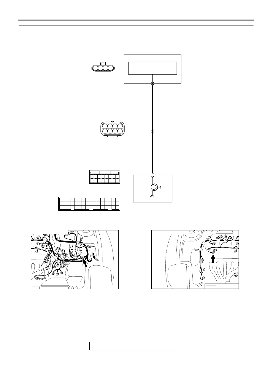
INSPECTION PROCEDURE 26: Generator output voltage is low (approximately 12.3 volts)
AK000676
4
3
2
6
3 4
7 8
1 2
5
1
BLA
CK-RED
BLA
CK-RED
ENGINE CONTROL
MODULE(ECM)<M/T>
OR
POWERTRAIN CONTROL
MODULE(PCM)<A/T>
GENERATOR
VOLTAGE
REGULATOR
B-45
1
2
B-13
MU802749
33<M/T>
8<A/T>
C-53<M/T>
(MU803771)
C-50<A/T>
(MU803784)
34
33
32
36
35
37
42
45
31
39
38
46
40 41
43 44
2
3 4
5 6
7 8
9
11 12 13 14 15 16 17 18 19 20
30
21 22 23
24 25
26 27 28 29
3132 33
34 35
1
10
AK000547AB
CONNECTOR:B-13
AK000546AC
CONNECTOR:C-45
MULTIPORT FUEL INJECTION (MFI) DIAGNOSIS
TSB Revision
MULTIPORT FUEL INJECTION (MFI) <2.4L ENGINE>
13A-401
CIRCUIT OPERATION
•
The EMC <M/T> or PCM <A/T> controls
generator out put current by duty-controlling
continuity between the generator G terminal
(terminal 1) and ground.
TROUBLESHOOTING HINTS (The most likely
causes for this charging system:)
•
Malfunction of the charging system.
•
Short circuit in the harness between generator G
terminal and ECM <M/T> or PCM <A/T>.
•
ECM <M/T> or PCM <A/T> failed.
DIAGNOSIS
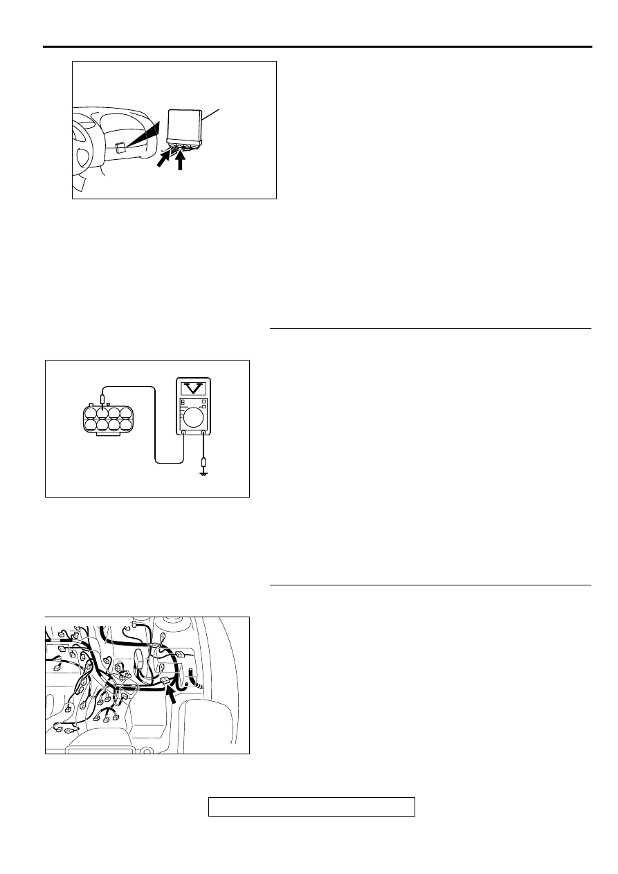
STEP 1. Check the voltage at generator intermediate
connector B-13 by backprobing
(1) Do not disconnect the connector B-13.
(2) Start the engine and run at idle.
(3) Measure the voltage between terminal 2 and ground by
backprobing.
a. Engine: warming up
b. Radiator fan: stopped
c. Headlight switch: OFF to ON
d. Rear defogger switch: OFF to ON
e. Stoplight switch: OFF to ON
•
Voltage rises by 0.2-3.5 volts.
(4) Turn the ignition switch to the "LOCK" (OFF) position.
Q: Is the voltage normal?
YES : Replace the generator. Then confirm that the
malfunction symptom is eliminated.
NO : Go to Step 2.
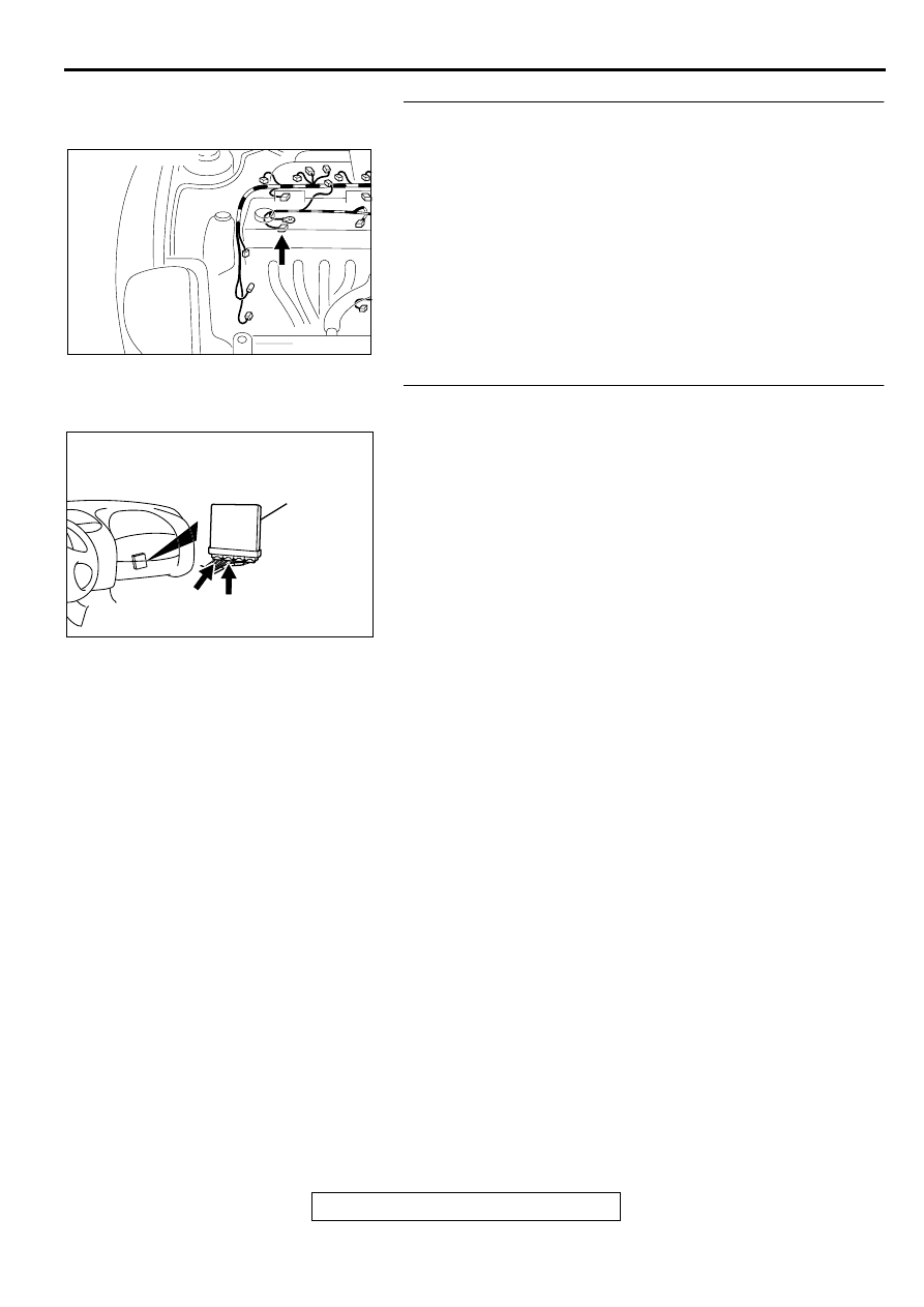
STEP 2. Check connector B-13 at generator intermediate
connector for damage.
Q: Is the connector in good condition?
YES : Go to Step 3.
NO : Repair or replace it. Refer to GROUP 00E, Harness
Connector Inspection (
). Then confirm that
the malfunction symptom is eliminated.
AK000280
C-50
C-53
ECM<M/T>
OR
PCM<A/T>
CONNECTORS:C-53<M/T>,C-50<A/T>
BK
AK000365 AB
B-13 CONNECTOR
HARNESS
SIDE VIEW
1 2 3 4
5 6 7 8
AK000547AB
CONNECTOR:B-13
MULTIPORT FUEL INJECTION (MFI) DIAGNOSIS
TSB Revision
MULTIPORT FUEL INJECTION (MFI) <2.4L ENGINE>
13A-402
STEP 3. Check connector B-45 at generator connector for
damage.
Q: Is the connector in good condition?
YES : Go to Step 4.
NO : Repair or replace it. Refer to GROUP 00E, Harness
Connector Inspection (
). Then confirm that
the malfunction symptom is eliminated.
STEP 4. Check connector C-53 at ECM <M/T> or connector
C-50 at PCM <A/T> for damage.
Q: Is the connector in good condition?
YES : Go to Step 5.
NO : Repair or replace it. Refer to GROUP 00E, Harness
Connector Inspection (
). Then confirm that
the malfunction symptom is eliminated.
AK000546AC
CONNECTOR:C-45
AK000280
C-50
C-53
ECM<M/T>
OR
PCM<A/T>
CONNECTORS:C-53<M/T>,C-50<A/T>
BK
Нет комментариевНе стесняйтесь поделиться с нами вашим ценным мнением.
Текст