Mitsubishi Eclipse / Eclipse Spyder (2000-2002). Service and repair manual — part 174
MULTIPORT FUEL INJECTION (MFI) DIAGNOSIS
TSB Revision
MULTIPORT FUEL INJECTION (MFI) <2.4L ENGINE>
13A-395
DIAGNOSIS
Required Special Tool:
MB991502: Scan Tool (MUT-II)
STEP 1. Check the exhaust gas with the engine at normal
operating temperature.
Q: After enough warm up, was the exhaust gas checked
enough?
YES : Go to Step 2.
NO : Check it again after enough warm up.
STEP 2. Check the following items.
(1) Check the following items.
a. Check all vacuum hoses and connectors.
b. Check electrical wires and connectors for obvious
problems.
c. Check the exhaust system for missing or damaged
parts.
Q: Are they normal?
YES : Go to Step 3.
NO : Repair or replace. Then confirm that the malfunction
symptom is eliminated.
STEP 3. Check the drive ability.
(1) Check if the malfunction symptom described on the
symptom chart is occurring.
Q: Is the drive
−
ability normal?
YES : Go to Step 4.
NO : Refer to, Trouble Symptom Chart (
STEP 4. Using scan tool MB991502, read the diagnostic
trouble code (DTC).
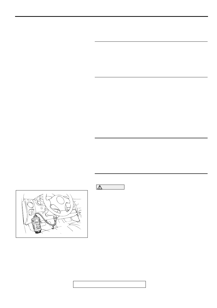
CAUTION
To prevent damage to scan tool MB991502, always turn the
ignition switch to the "LOCK" (OFF) position before
connecting or disconnecting scan tool MB991502.
(1) Connect scan tool MB991502 to the data link connector.
(2) Turn the ignition switch to the "ON" position.
(3) Read the DTC.
(4) Turn the ignition switch to the "LOCK" (OFF) position.
Q: Is the DTC is output?
YES : Refer to, Diagnostic Trouble Code Chart (
NO : Go to Step 5.
AKX01177
16 PIN
MB991502
AB

MULTIPORT FUEL INJECTION (MFI) DIAGNOSIS
TSB Revision
MULTIPORT FUEL INJECTION (MFI) <2.4L ENGINE>
13A-396
STEP 5. Check the ignition timing.
Refer to GROUP 11A, On-vehicle Service
−
Ignition Timing
Check (
Q: Is the ignition timing normal?
YES : Go to Step 6.
NO : Check that the crankshaft position sensor and timing
belt cover are in the correct position. Then confirm
that the malfunction symptom is eliminated.
STEP 6. Using scan tool MB991502, check data list.
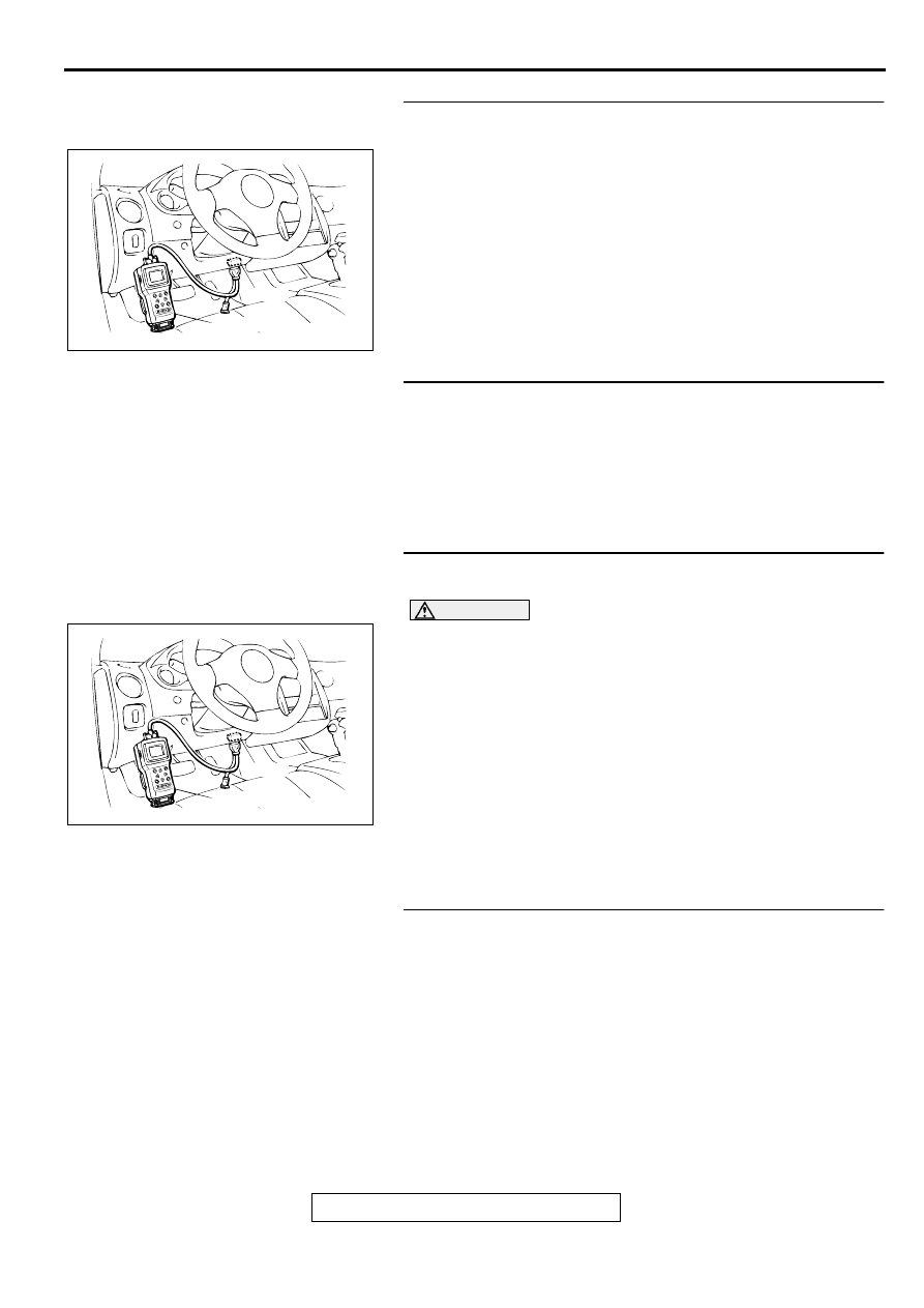
CAUTION
To prevent damage to scan tool MB991502, always turn the
ignition switch to the "LOCK" (OFF) position before
connecting or disconnecting scan tool MB991502.
(1) Connect scan tool MB991502 to the data link connector.
(2) Turn the ignition switch to the "ON" position.
(3) Check the following items in the data list. Refer to, Data List
Reference Table (
a. Item 21: Engine Coolant Temperature Sensor.
b. Item 13: Intake Air Temperature Sensor.
c. Item 25: Barometric pressure Sensor.
d. Item 59: Heated Oxygen Sensor (rear)
(4) Turn the ignition switch to the "LOCK" (OFF) position.
Q: Is the sensor operating properly?
YES : Go to Step 7.
NO : Repair or replace. Then confirm that the malfunction
symptom is eliminated.
STEP 7. Using scan tool MB991502, check data list item 11:
heated oxygen sensor (front).
(1) Start the engine and run at idle.
(2) Set scan tool MB991502 to the data reading mode for item
11, Heated Oxygen Sensor (front).
•
Warm up the engine. When the engine is decelerated
suddenly from 4000 r/min, the output voltage should
increase from 200 mV or less to 600
−
1000 mV in a few
seconds.
(3) Turn the ignition switch to the "LOCK" (OFF) position.
Q: Is the sensor operating properly?
YES : Go to Step 8.
NO : Refer to, DTC P0130
−
Oxygen Sensor Circuit
Malfunction (sensor 1) (
), DTC P0133
−
Oxygen Sensor Circuit Slow Response (sensor 1)
(
).
AKX01177
16 PIN
MB991502
AB
AKX01177
16 PIN
MB991502
AB
MULTIPORT FUEL INJECTION (MFI) DIAGNOSIS
TSB Revision
MULTIPORT FUEL INJECTION (MFI) <2.4L ENGINE>
13A-397
STEP 8. Using scan tool MB991502, check data list item 11:
Heated oxygen sensor (front).
(1) Start the engine and run at idle.
(2) Set scan tool MB991502 to the data reading mode for item
11, Heated Oxygen Sensor (front).
•
Voltage should fluctuate between 0
−
0.4 volts and 0.6 -
1.0 volts while after the engine has been warmed.
(3) Turn the ignition switch to the "LOCK" (OFF) position.
Q: Is the sensor operating properly?
YES : Go to Step 9.
NO : Go to Step 11.
STEP 9. Check the EGR system.
Refer to GROUP 17, Emission Control System
−
EGR System
Check (
Q: Is the EGR system normal?
YES : Go to Step 10.
NO : Repair or replace. Then confirm that the malfunction
symptom is eliminated.
STEP 10. Using scan tool MB991502, check data list item
59: Heated oxygen sensor (rear).
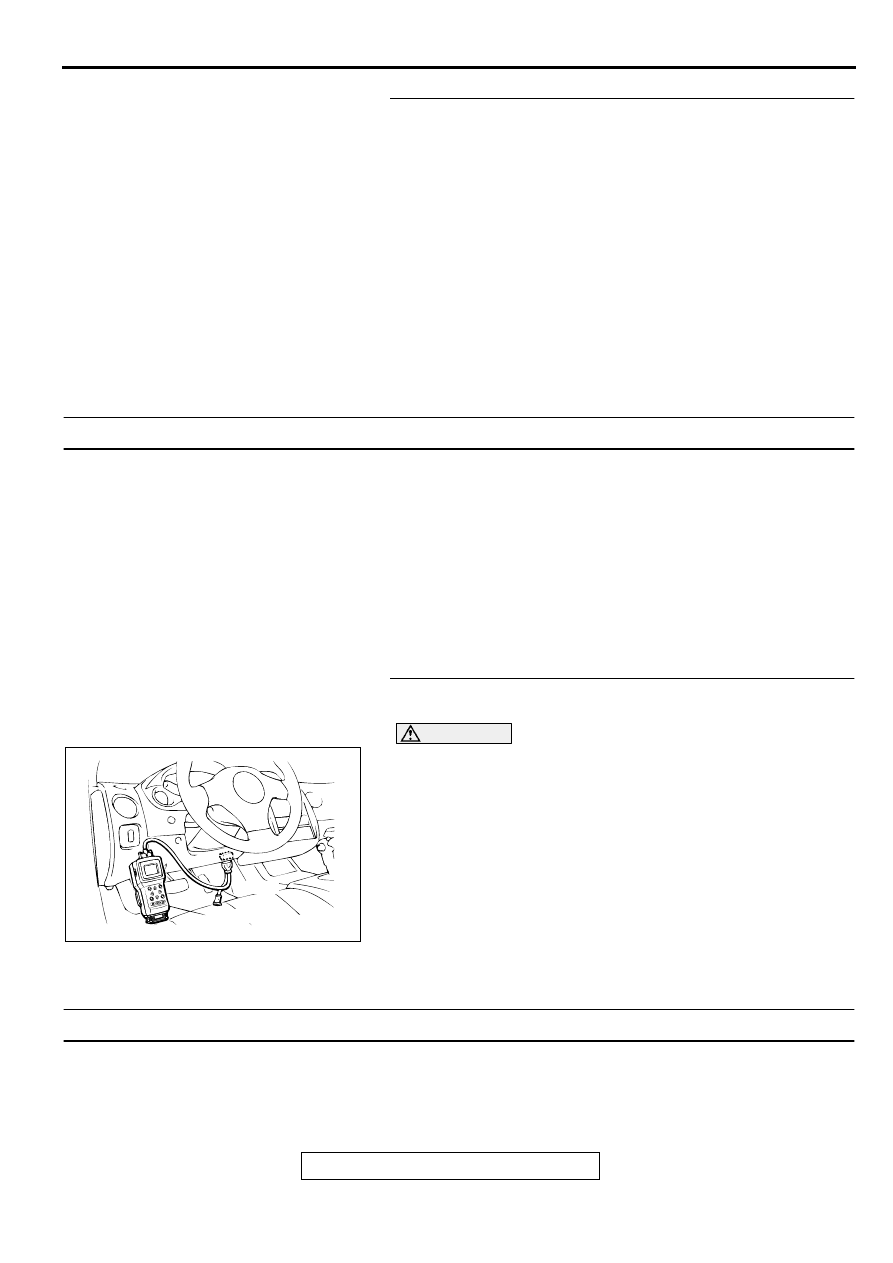
CAUTION
To prevent damage to scan tool MB991502, always turn the
ignition switch to the "LOCK" (OFF) position before
connecting or disconnecting scan tool MB991502.
(1) Connect scan tool MB991502 to the data link connector.
(2) Start the engine and run at idle.
(3) Set scan tool MB991502 to the data reading mode for item
59, Heated Oxygen Sensor (rear).
•
Average voltage should be 0.6 volts or less, when idling.
(4) Turn the ignition switch to the "LOCK" (OFF) position.
Q: Is the sensor operating properly?
YES : Go to Step 12.
NO : Replace the heated oxygen sensor (front). Then
confirm that the malfunction symptom is eliminated.
STEP 11. Check the fuel pressure.
Refer to, Fuel Pressure Test (
Q: Is the fuel pressure normal?
YES : Go to Step 12.
NO : Repair or replace. Then confirm that the malfunction
symptom is eliminated.
AKX01177
16 PIN
MB991502
AB
AKX01177
16 PIN
MB991502
AB
MULTIPORT FUEL INJECTION (MFI) DIAGNOSIS
TSB Revision
MULTIPORT FUEL INJECTION (MFI) <2.4L ENGINE>
13A-398
STEP 12. Check the following items.
(1) Check the following items, and repair or replace the
defective items.
a. Check the injectors for fuel leakage.
b. Check the ignition coil, spark plugs, spark plug cables.
c. Check compression pressure.
d. Check the positive crankcase ventilation system.
e. Check the evaporative emission control system.
(2) Then check the malfunction symptom.
Q: Is the malfunction symptom is eliminated?
YES : The check is completed.
NO : Replace the catalytic converter. Then confirm that the
malfunction symptom is eliminated.
INSPECTION PROCEDURE 24: Purge Flow Test of the Evaporative Emission Canister Failure.
COMMENT
•
The test fails when the purge line or purge port is
clogged or if the evaporative emission purge
solenoid fails.
TROUBLESHOOTING HINTS (The most likely
causes for this case:)
•
Purge line or purge port is clogged.
•
Malfunction of the evaporative emission purge
solenoid.
•
Evaporative emission canister is clogged.
DIAGNOSIS
Required Special Tool:
MB991502: Scan Tool (MUT-II)
STEP 1. Using scan tool MB991502, read the diagnostic
trouble code (DTC).
CAUTION
To prevent damage to scan tool MB991502, always turn the
ignition switch to the "LOCK" (OFF) position before
connecting or disconnecting scan tool MB991502.
(1) Connect scan tool MB991502 to the data link connector.
(2) Turn the ignition switch to the "ON" position.
(3) Read the DTC.
(4) Turn the ignition switch to the "LOCK" (OFF) position.
Q: Is the DTC is output?
YES : Refer to, Diagnostic Trouble Code Chart (
NO : Refer to GROUP 17, Emission Control System-Purge
Control System Check (Purge Flow Check) (
INSPECTION PROCEDURE 25: Pressure Test of the Evaporative System Failure.
COMMENT
•
The test fails if there is a leak from the fuel tank or
vapor line.
TROUBLESHOOTING HINTS (The most likely
causes for this case:)
•
Loose fuel tank filler tube cap.
•
Broken seal in fuel tank, vapor line evaporative
emission canister.
AKX01177
16 PIN
MB991502
AB
Нет комментариевНе стесняйтесь поделиться с нами вашим ценным мнением.
Текст