Mitsubishi Eclipse / Eclipse Spyder (2000-2002). Service and repair manual — part 389
AUTO-CRUISE CONTROL
TSB Revision
ENGINE AND EMISSION CONTROL
17-75
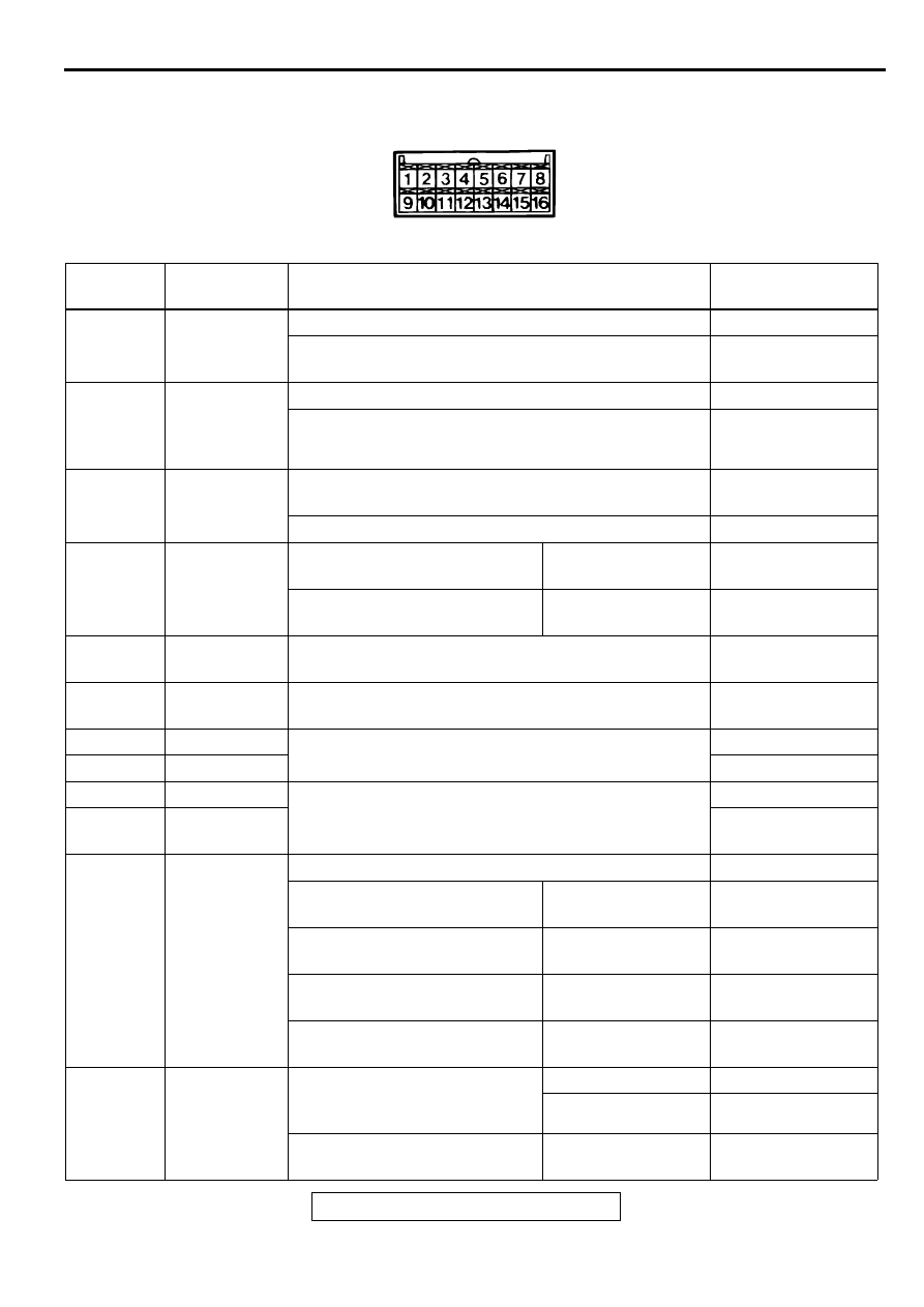
CHECK AUTO-CRUISE CONTROL-ECU TERMINALS
M1172002700063
ACX02234
TERMINAL
NO.
INSPECTION
ITEM
INSPECTION CONDITIONS
NORMAL
CONDITION
1
Throttle
position
sensor input
When accelerator pedal is fully depressed
4.0
−
5.5 V
When accelerator pedal is released
0.3
−
1.0 V <2.4L>
0.5
−
0.7 V <3.0L>
2
Powertrain
control module
output (Idle
switch)
When accelerator pedal is depressed
4.0
−
5.5 V
When accelerator pedal is not depressed
2.5 V or less
3
A/T control
output
No "OD-OFF" request
Battery positive
voltage
"OD-OFF" request
0 V
4
Stoplight
switch input
When brake pedal is depressed When stoplight
switch is ON
Battery positive
voltage
When brake pedal is not
depressed
When stoplight
switch is OFF
0 V
5
Pump power
supply
Ignition switch: "ON" position
Stoplight switch: OFF
10 V or more
6
ECU power
supply
Ignition switch: "ON" position
Battery positive
voltage
7
Release valve
When decelerating with the "SET" switch while driving
at constant speed
1 V or less
8Control valve
10 V or more
7
Release valve
When cancelling constant speed driving with the
"CANCEL" switch
10 V or more
8Control valve
Battery positive
voltage
9
Auto-cruise
control switch
input
When main switch is "ON"
Approximately 7.0 V
When input switch has not been
operated
When all switches
are OFF
3.5
−
5.0 V
When input switch is pushed
down
When "SET" switch
is ON
0.4
−
2.3 V
When input switch is pushed up When "RESUME"
switch is ON
2.3
−
3.5 V
When input switch is pulled
forward
When "CANCEL"
switch is ON
0.4 V or less
10
Vehicle speed
sensor input
When vehicle is moved forwards
and backwards, sensor turns
ON and OFF repeatedly
When sensor is ON
0 V
When sensor is OFF 4.5 V or more
Ignition switch: "ON" position
Move the vehicle
forward slowly
0 and 8
−
12 V
alternate

AUTO-CRUISE CONTROL
TSB Revision
ENGINE AND EMISSION CONTROL
17-76
11
Diagnosis
control input
When ignition switch is "ON" position
4 V or more
12
ACC power
supply
When ignition switch is in "ACC" position
Main switch: "ON"
Battery positive
voltage
13
Clutch pedal
position switch
input <M/T>
When pedal is not depressed
When clutch pedal
position switch is
OFF
Battery positive
voltage
When pedal is depressed
When clutch pedal
position switch is ON
0 V
Park/neutral
position switch
input <A/T>
When select lever is in a position
other than N range
When park/neutral
position switch is
OFF
Battery positive
voltage
When select lever is in N range
When park/neutral
position switch is ON
0 V
14
Ground
At any time
0 V
15
Indicator light
input (inside
combination
meter)
When indicator light is illuminated
0 V
When indicator light is switch off
Battery positive
voltage
16
Auto-cruise
vacuum pump
motor input
When driving at constant speed
using the "SET" switch
Motor stopped/
running
Battery positive
voltage/0 V
When accelerating with the
"RESUME" switch while driving
at constant speed
Motor stopped/
running
Battery positive
voltage/0 V
When decelerating with the
"SET" switch while driving at
constant speed
Motor stopped
Battery positive
voltage
When cancelling constant speed
driving with the "CANCEL"
switch
Motor stopped
Battery positive
voltage
TERMINAL
NO.
INSPECTION
ITEM
INSPECTION CONDITIONS
NORMAL
CONDITION

AUTO-CRUISE CONTROL
TSB Revision
ENGINE AND EMISSION CONTROL
17-77
ON-VEHICLE SERVICE
AUTO-CRUISE CONTROL SWITCH CHECK
M1172001100079
1. Turn the ignition switch to "ON" position.
2. Check that the indicator light within the combination meter
illuminates when the main switch is switched "ON".
AUTO-CRUISE CONTROL SETTING
1. Switch "ON" the main switch.
2. Drive at the desired speed, above approximately 40 km/h.
(25 mph)
3. Push the auto-cruise control switch in the direction of arrow.
4. Check to be sure that when the switch is released the speed
is the desired constant speed.
NOTE: If the vehicles speed decreases to approximately 15
km/h (9 mph) below the set speed because of climbing a hill
for example, the auto-cruise control will be cancelled.
SPEED-INCREASE SETTING
1. Set to the desired speed.
2. Push the auto-cruise control switch in the direction of arrow.
3. Check to be sure that acceleration continues while the
switch is held, and that after it is released the constant
speed at the time when it was released becomes the driving
speed.
NOTE: Acceleration can be continued even if the vehicle
speed has passed the high-speed limit [approximately 200
km/h (124 mph)].
But the speed when the auto-cruise control switch is
released will be recorded as the high-speed limit.
AC001491
AUTO-CRUISE
INDICATOR LIGHT
AB
ACX01172
AD
ACX01172
AE
AUTO-CRUISE CONTROL
TSB Revision
ENGINE AND EMISSION CONTROL
17-78
SPEED-REDUCTION SETTING
1. Set to the desired speed.
2. Push the auto-cruise control switch in the direction of arrow.
3. Check to be sure that deceleration continues while the
switch is pressed, and that after it is released the constant
speed at the time when it was released becomes the driving
speed.
NOTE: When the vehicle speed reaches the low limit
[approximately 40 km/h (25 mph)] during deceleration, the
auto-cruise control will be cancelled.
RETURN TO THE SET SPEED BEFORE
CANCELLATION AND AUTO-CRUISE CONTROL
CANCELLATION
1. Set the auto-cruise speed control.
2. When any of the following operations are performed while at
constant speed during auto-cruise control, check if normal
driving is resumed and deceleration occurs.
(1) The auto-cruise control switch is pushed in the direction
of arrow.
(2) The brake pedal is depressed.
(3) The clutch pedal is depressed. (M/T)
(4) The selector lever is moved to the "N" range. (A/T)
3. At a vehicle speed of 40 km/h (25 mph) or higher, check if
when the "RESUME" switch is switched "ON," the vehicle
speed returns to the speed before auto-cruise control driving
was cancelled, and constant speed driving occurs.
4. When the main switch is turned to "OFF" while driving at
constant speed, check if normal driving is resumed and
deceleration occurs.
AUTO-CRUISE CONTROL SYSTEM COMPONENT
CHECK
M1172001700071
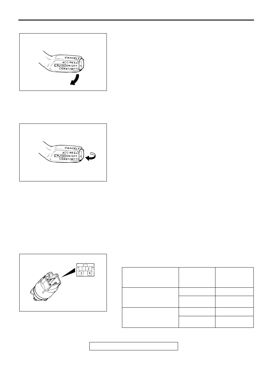
STOPLIGHT SWITCH
1. Disconnect the connector.
2. Check for continuity between the terminals of the switch.
ACX01172
AD
ACX01172
AG
MEASUREMENT
CONDITIONS
TERMINAL
CONNECTOR
OF TESTER
SPECIFIED
CONDITION
When brake pedal is
depressed. (for stoplight
circuit)
1
−
2
Continuity
3
−
4
No continuity
When brake pedal is not
depressed. (for auto-
cruise control circuit)
1
−
2
No continuity
3
−
4
Continuity
ACX01180 AB
Нет комментариевНе стесняйтесь поделиться с нами вашим ценным мнением.
Текст