Mitsubishi Eclipse / Eclipse Spyder (2000-2002). Service and repair manual — part 387
AUTO-CRUISE CONTROL
TSB Revision
ENGINE AND EMISSION CONTROL
17-67
INSPECTION PROCEDURE 8: Auto-cruise Control Indicator Light inside Combination Meter does not
Illuminate. (However, Auto-cruise Control is Normal.)
AC005117
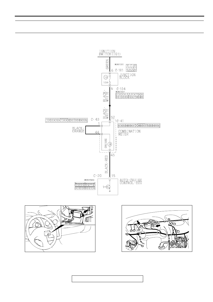
Auto-cruise Control Indicator Light Drive Circuit
AB
AC001451
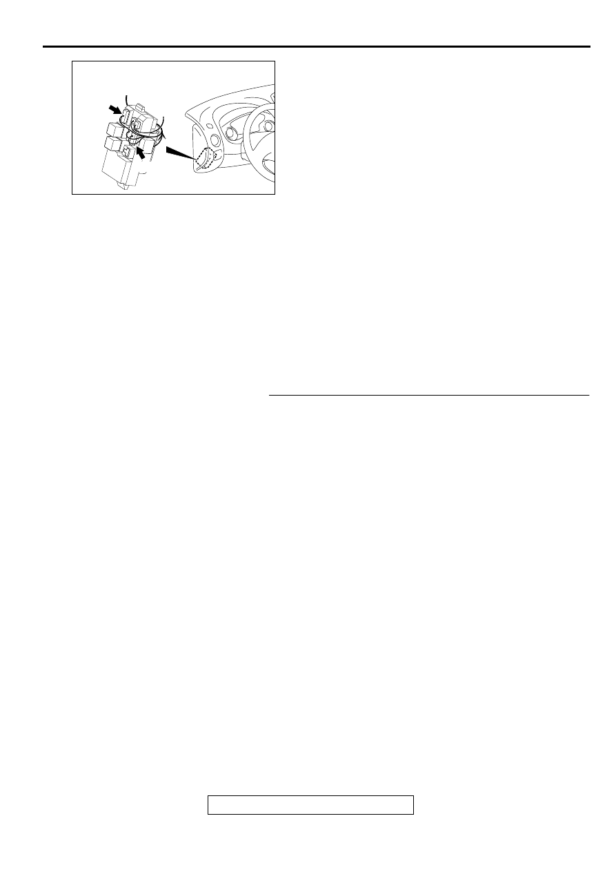
CONNECTOR: C-20
AB
AC003552 AI
CONNECTORS: C-41, C-43
C-41
C-43
AUTO-CRUISE CONTROL
TSB Revision
ENGINE AND EMISSION CONTROL
17-68
CIRCUIT OPERATION
The power for the auto-cruise indicator in the
combination meter is supplied from the ignition
switch (IG1).
When the auto-cruise control system is operating,
the transistor inside the auto-cruise control-ECU
illuminates the auto-cruise indicator through ECU
terminal number 15.
TECHNICAL DESCRIPTION (COMMENT)
The cause is probably the malfunction of the
indicator bulb or the malfunction of the connector or
harness.
TROUBLESHOOTING HINTS
•
Malfunction of the indicator bulb.
•
Damaged harness or connector.
•
Malfunction of the auto-cruise control-ECU.
DIAGNOSIS
Required Special Tool:
•
MB991223: Harness Set
STEP 1. Check the auto-cruise control indicator bulb.
(1) Remove the combination meter.
Refer to GROUP54A, Combination Meter Assembly and
Vehicle Speed Sensor
.
(2) Check the auto-cruise control indicator bulb.
Q: Is the bulb blown?
YES : Replace the bulb.
Then check that the malfunction is eliminated.
NO : Go to Step 2.
AC001995 AP
CONNECTORS: C-101, C-104
C-104
C-101
JUNCTION BLOCK
(FRONT VIEW)
AUTO-CRUISE CONTROL
TSB Revision
ENGINE AND EMISSION CONTROL
17-69
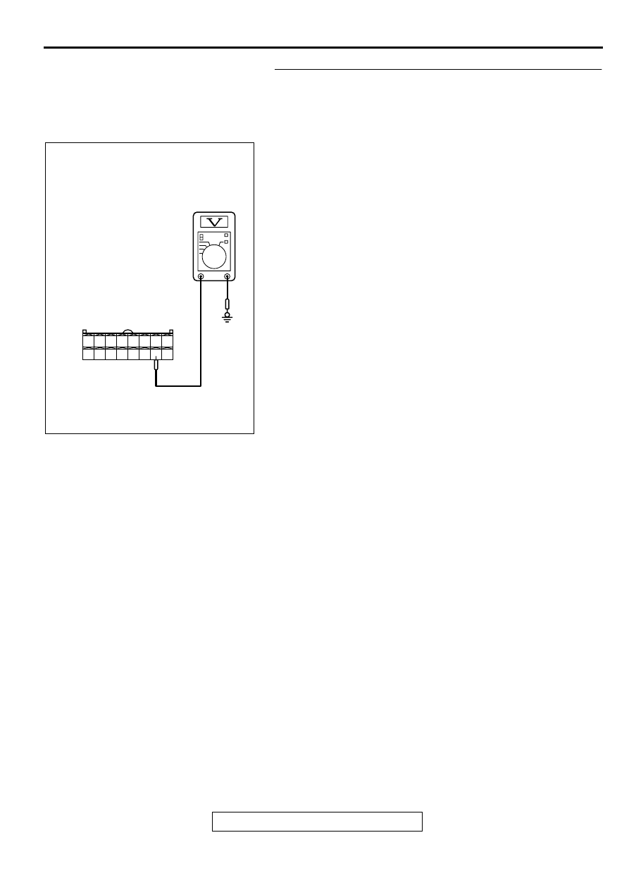
STEP 2. Check the output circuit voltage at auto-cruise
control-ECU connector C-20 by backprobing.
(1) Do not disconnect auto-cruise control switch connector C-
20.
(2) Turn the ignition switch to "ON" position.
(3) Measure the voltage between terminal 15 and ground by
backprobing.
(4) Turn the ignition switch to "LOCK" (OFF) position.
Q: Is the voltage approximately battery positive voltage?
YES : Check that the malfunction is eliminated.
If the malfunction is eliminated, replace the auto-
cruise control-ECU. (Refer to
.)
Then check that the malfunction is eliminated.
NO : Go to Step 3.
1 2 3 4 5 6 7 8
9 10 11 12 13 14 15 16
AC002355
C-20 CONNECTOR
HARNESS SIDE VIEW
AD
AUTO-CRUISE CONTROL
TSB Revision
ENGINE AND EMISSION CONTROL
17-70
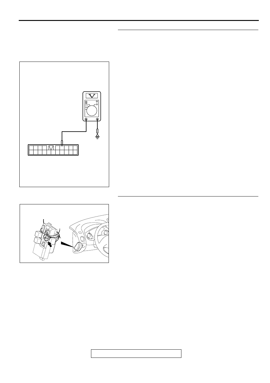
STEP 3. Check the output circuit voltage at junction block
connector C-104 by backprobing.
(1) Do not disconnect auto-cruise control switch connector C-
104.
(2) Turn the ignition switch to "ON" position.
(3) Measure the voltage between terminal 6 and ground by
backprobing.
(4) Turn the ignition switch to "LOCK" (OFF) position.
Q: Is the voltage approximately battery positive voltage?
YES : Go to Step 5.
NO : Go to Step 4.
STEP 4. Check junction block connector C-104.
Q: Is the connector damaged?
YES : Repair or replace connector.
Refer to GROUP 00E, Harness Connector Inspection
.
Then check that the malfunction is eliminated.
NO : Replace the junction block.
Then check that the malfunction is eliminated.
AC002391
1 2 3 4
5 6 7 8 9
10 1112 1314 15 16 1718 19 20
C-104 CONNECTOR
HARNESS SIDE VIEW
AD
AC001995 AW
CONNECTOR: C-104
JUNCTION BLOCK
(FRONT VIEW)
Нет комментариевНе стесняйтесь поделиться с нами вашим ценным мнением.
Текст