Mitsubishi Eclipse / Eclipse Spyder (2000-2002). Service and repair manual — part 250
MULTIPORT FUEL INJECTION (MFI) DIAGNOSIS
TSB Revision
MULTIPORT FUEL INJECTION (MFI) <3.0L ENGINE>
13B-199
•
Intake air temperature is higher than 60
°
C (140
°
F) when the engine is started.
•
Under the closed loop air/fuel ratio control.
•
Intake air temperature is higher than -10
°
C (14
°
F).
•
Barometric pressure is higher than 76kPa (11
psi).
•
Volume air flow sensor output frequency is 75 Hz
or more.
Judgment Criteria
•
Long-term fuel trim has continued to be higher
than +12.5 for 5 seconds.
or
•
Short-term fuel trim has continued to be higher
than +17.4 for 5 seconds.
Check Area
•
Engine coolant temperature is higher than
approximately 100
°
C (212
°
F) when the engine
is started.
•
Intake air temperature is higher than 60
°
C
(140
°
F) when the engine is started.
•
Under the closed loop air/fuel ratio control.
•
Intake air temperature is higher than -10
°
C
(14
°
F).
•
Barometric pressure is higher than 76kPa (11
psi).
•
Volume air flow sensor output frequency is 75 Hz
or less.
Judgment Criteria
•
Long-term fuel trim has continued to be higher
than +12.5 for 5 seconds.
or
•
Short-term fuel trim has continued to be higher
than +22.4 for 5 seconds.
Check Area
•
Under the closed loop air/fuel ratio control.
•
The right bank heated oxygen sensor (front) is
active.
Judgment Criteria
•
Long-term fuel trim has continued to be higher
than +12.5 for 5 seconds.
or
•
Short-term fuel trim has continued to be higher
than +25.0 for 5 seconds.
TROUBLESHOOTING HINTS (The most likely
causes for this code to be set are:)
•
Volume air flow sensor failed.
•
Injector (Number 1, 3, 5) failed.
•
Incorrect fuel pressure
•
Air drawn in from gaps in gasket, seals, etc.
•
Right bank heated oxygen sensor failed.
•
Engine coolant temperature sensor failed.
•
Intake air temperature sensor failed.
•
Barometric pressure sensor failed.
•
Use of incorrect or contaminated fuel.
•
ECM failed. <M/T>
•
PCM failed. <A/T>
DIAGNOSIS
Required Special Tools
MB991502: Scan Tool (MUT-II)
STEP 1. Check the exhaust leaks.
Q: Are there any abnormalities?
YES : Go to Step 2.
NO : Repair it. Then go to Step 16.
STEP 2. Check the intake system vacuum leak.
Q: Are there any abnormalities?

MULTIPORT FUEL INJECTION (MFI) DIAGNOSIS
TSB Revision
MULTIPORT FUEL INJECTION (MFI) <3.0L ENGINE>
13B-200
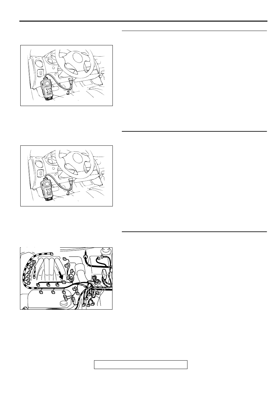
STEP 3. Using scan tool MB991502, check data list item 12:
Volume Air Flow Sensor.
CAUTION
To prevent damage to scan tool MB991502, always turn the
ignition switch to the "LOCK" (OFF) position before
connecting or disconnecting scan tool MB991502.
(1) Connect scan tool MB991502 to the data link connector.
(2) Start the engine and run at idle.
(3) Set scan tool MB991502 to the data reading mode for item
12, Volume Air Flow Sensor.
(4) Warm up the engine to normal operating temperature: 80
°
C to 96
°
C(176
°
F to 205
°
F).
•
When idling, between 17 and 46 Hz (between 2.2 and
5.7 g/s).
•
When 2,500 r/min, between 63 and 103 Hz (between
9.0 and 14.7 g/s).
(5) Turn the ignition switch to the "LOCK" (OFF) position.
Q: Is the sensor operating properly?
YES : Go to Step 4.
NO : Refer to, DTC P0101
−
Volume Air Flow Circuit
Range/Performance Problem (
),DTC P0102
−
Volume Air Flow Circuit Low Input (
), DTC
P0103 - Volume Air Flow Circuit High Input (
STEP 4. Using scan tool MB991502, check data list item 13:
Intake Air Temperature Sensor.
(1) Turn the ignition switch to the "ON" position.
(2) Set scan tool MB991502 to the data reading mode for item
13, Intake Air Temperature Sensor.
•
The intake air temperature and temperature shown with
the scan tool should approximately match.
(3) Turn the ignition switch to the "LOCK" (OFF) position.
Q: Is the sensor operating properly?
YES : Go to Step 5.
NO : Refer to, DTC P0111
−
Intake Air Temperature Circuit
Range/Performance Problem (
AKX01177
16 PIN
MB991502
AB
AKX01177
16 PIN
MB991502
AB
MULTIPORT FUEL INJECTION (MFI) DIAGNOSIS
TSB Revision
MULTIPORT FUEL INJECTION (MFI) <3.0L ENGINE>
13B-201
STEP 5. Using scan tool MB991502, check data list item 21:
Engine Coolant Temperature Sensor.
(1) Turn the ignition switch to the "ON" position.
(2) Set scan tool MB991502 to the data reading mode for item
21, Engine Coolant Temperature Sensor.
•
The engine coolant temperature and temperature
shown with the scan tool should approximately match.
(3) Turn the ignition switch to the "LOCK" (OFF) position.
Q: Is the sensor operating properly?
YES : Go to Step 6.
NO : Refer to, DTC P0115
−
Engine Coolant Temperature
Circuit High Input (
), DTC P0116
−
Engine
Coolant Temperature Circuit Range/Performance
Problem (
), DTC P0117
−
Engine Coolant
Temperature Circuit Low Input (
STEP 6. Using scan tool MB991502, check data list item 25:
Barometric Pressure Sensor.
(1) Turn the ignition switch to the "ON" position.
(2) Set scan tool MB991502 to the data reading mode for item
25, Barometric Pressure Sensor.
•
When altitude is 0 m (0 foot), 101 kPa.
•
When altitude is 600 m (1,969 feet), 95 kPa.
•
When altitude is 1,200 m (3,937 feet), 88 kPa.
•
When altitude is 1,800 m (5,906 feet), 81 kPa.
(3) Turn the ignition switch to the "LOCK" (OFF) position.
Q: Is the sensor operating properly?
YES : Go to Step 7.
NO : Refer to, DTC P0107
−
Barometric Pressure Circuit
Low Input (
), DTC P0108
−
Barometric
Pressure Circuit High Input (
STEP 7. Check connector B-48 at injector intermediate
connector for damage.
Q: Is the connector in good condition?
YES : Go to Step 8.
NO : Repair or replace it. Refer to GROUP 00E, Harness
Connector Inspection (
). Then go to Step 16.
AKX01177
16 PIN
MB991502
AB
AKX01177
16 PIN
MB991502
AB
AK000209AC
CONNECTOR:B-48
MULTIPORT FUEL INJECTION (MFI) DIAGNOSIS
TSB Revision
MULTIPORT FUEL INJECTION (MFI) <3.0L ENGINE>
13B-202
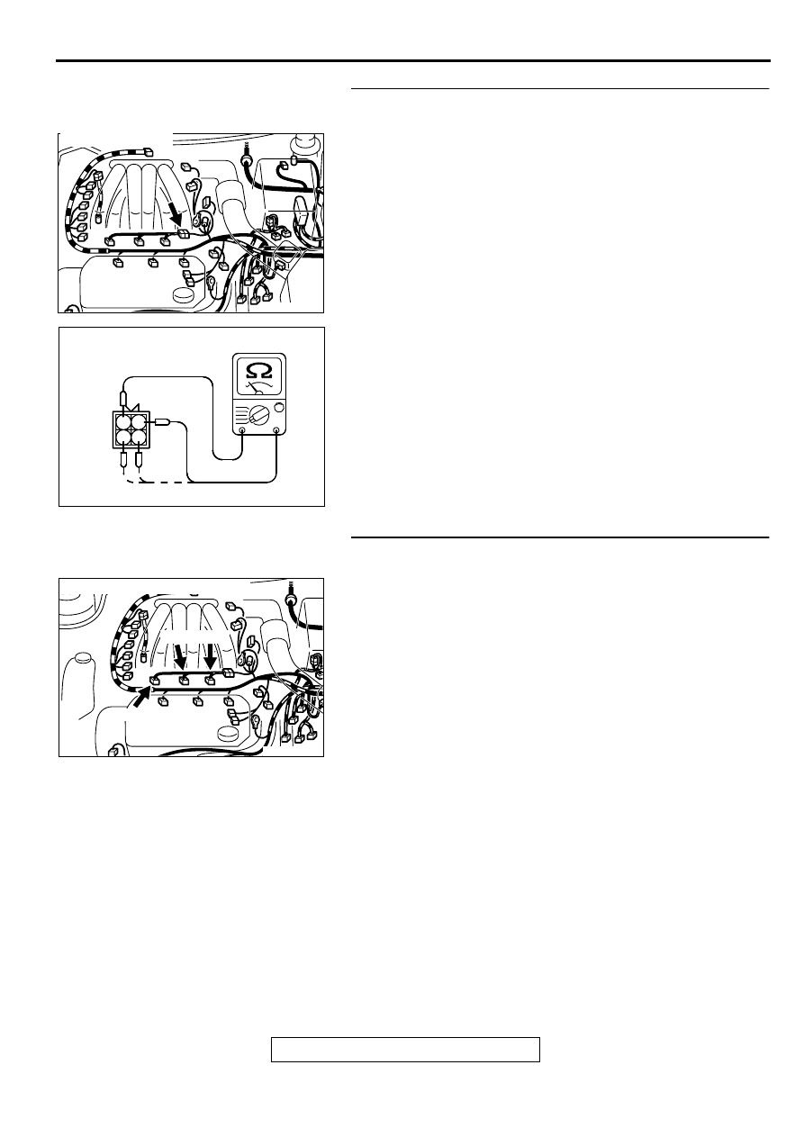
STEP 8. Check the right bank injector resistance at
intermediate connector B-48.
(1) Disconnect the injector intermediate connector B-48.
(2) Measure the resistance between each male connector side
connector terminal.
a. Measure the resistance between terminal 1 and 2 when
measuring No.1 cylinder.
b. Measure the resistance between terminal 1 and 3 when
measuring No.3 cylinder.
c. Measure the resistance between terminal 1 and 4 when
measuring No.5 cylinder.
•
Resistance should be between 13 and 16 ohm [at 20
°
C
(68
°
F)].
Q: Is the resistance normal?
YES : Go to Step 11.
NO : Go to Step 9.
STEP 9. Check connector B-01, B-05, B-26 at right bank
injector for damage.
(1) Remove the intake manifold.
(2) Check the injector connector, which deviates from the
standard value at Step 8.
Q: Is the connector in good condition?
YES : Go to Step 10.
NO : Repair or replace it. Refer to GROUP 00E, Harness
Connector Inspection (
). Then go to Step 16.
AK000209AC
CONNECTOR:B-48
AK000240AB
INJECTOR
INTERMEDIATE
CONNECTOR
1 2
3 4
AK000210AB
B-05 B-26
B-01
CONNECTORS : B-01, B-05, B-26
Нет комментариевНе стесняйтесь поделиться с нами вашим ценным мнением.
Текст