Mitsubishi Eclipse / Eclipse Spyder (2000-2002). Service and repair manual — part 248

MULTIPORT FUEL INJECTION (MFI) DIAGNOSIS
TSB Revision
MULTIPORT FUEL INJECTION (MFI) <3.0L ENGINE>
13B-191
STEP 1. Using scan tool MB991502, check data list item 59:
Heated Oxygen Sensor Bank 2, Sensor 2 (left rear).
CAUTION
To prevent damage to scan tool MB991502, always turn the
ignition switch to the "LOCK" (OFF) position before
connecting or disconnecting scan tool MB991502.
(1) Connect scan tool MB991502 to the data link connector.
(2) Start the engine and run at idle.
(3) Set scan tool MB991502 to the data reading mode for item
59, Heated Oxygen Sensor Bank 2, Sensor 2 (left rear).
(4) Warm up the engine.
•
After increasing the output voltage 0.15 volts or more by
the engine revving, finish it. Then confirm that the output
voltage reduces to 0.15 volts or less within 3 seconds.
(5) Turn the ignition switch to the "LOCK" (OFF) position.
Q: Is the sensor operating properly?
YES : It can be assumed that this malfunction is intermittent.
Refer to GROUP 00, How to Use Troubleshooting/
Inspection Service Points (
NO : Replace the left bank heated oxygen sensor (rear).
Then go to Step 2.
STEP 2. Test the OBD-II drive cycle.
(1) Carry out a test drive with the drive cycle pattern. Refer to,
Procedure 6
−
Other Monitor (
).
(2) Check the diagnostic trouble code (DTC).
Q: Is the DTC P0159 is output?
YES : Retry the troubleshooting.
NO : The inspection is complete.
AKX01177
16 PIN
MB991502
AB
MULTIPORT FUEL INJECTION (MFI) DIAGNOSIS
TSB Revision
MULTIPORT FUEL INJECTION (MFI) <3.0L ENGINE>
13B-192
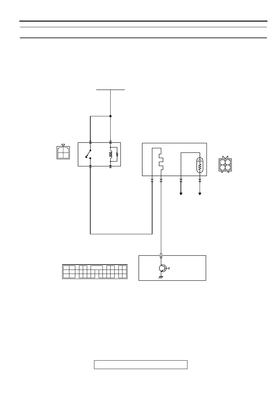
DTC P0161: O
2
Sensor Heater Circuit Malfunction (bank 2 sensor 2)
AK000697
3 4
1 2
RED-
WHITE
RED-
WHITE
RED-
WHITE
RED
BLUE-WHITE
3 4
1 2
BATTERY
A-21X
MFI
RELAY
LEFT BANK HEATED
OXYGEN SENSOR(REAR)
TO ECM
OR PCM
TO ECM
OR PCM
1
2
3
4
4
2
1
3
ENGINE CONTROL
MODULE(ECM)<M/T>
OR
POWERTRAIN CONTROL
MODULE(PCM)<A/T>
26
B-23
MU802665
C-51<M/T>,C-52<A/T>
(MU803784)
2
3 4
5 6
7 8
9
11 12 13 14 15 16 17 18 19 20
30
21 22 23
24 25
26 27 28 29
3132 33
34 35
1
10
MULTIPORT FUEL INJECTION (MFI) DIAGNOSIS
TSB Revision
MULTIPORT FUEL INJECTION (MFI) <3.0L ENGINE>
13B-193
CIRCUIT OPERATION
•
Power is supplied from the MFI relay (terminal 1)
to the left bank heated oxygen sensor (rear)
heater.
•
The ECM (terminal 26) <M/T> or PCM (terminal
26) <A/T> controls continuity to the left bank
heated oxygen sensor (rear) heater by turning
the power transistor in the ECM <M/T> or PCM
<A/T> "ON" and "OFF."
BACKGROUND
•
The ECM <M/T> or PCM <A/T> checks whether
the heater current is within a specified range
when the heater is energized.
DTC SET CONDITIONS
Check Conditions
•
Engine coolant temperature is higher than 20
°
C
(68
°
F).
•
While the left bank heated oxygen sensor (rear)
heater is on.
•
Battery positive voltage is between 11 and 16
volts.
Judgment Criteria
•
Heater current of the left bank heated oxygen
sensor (rear) heater has continued to be lower
than 0.2 ampere or higher than 3.5 ampere for 6
seconds.
•
Only one monitor during one drive cycle
TROUBLESHOOTING HINTS (The most likely
causes for this code to be set are:)
•
Open or shorted left bank heated oxygen sensor
(rear) heater circuit.
•
Open circuit in left bank heated oxygen sensor
(rear) heater.
•
ECM failed. <M/T>
•
PCM failed. <A/T>
DIAGNOSIS
Required Special Tools
MB991316: Test Harness Set
ACX02488
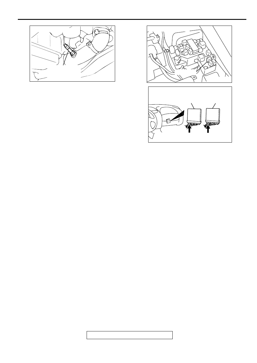
CONNECTOR : B-23
LEFT BANK
HEATED OXYGEN
SENSOR (REAR)
AC
AK000226
AK000226AB
CONNECTOR : A-21X
MFI RELAY
AK000225
CONNECTOR : C-51<M/T>, C-52<A/T>
C-52
C-51
PCM<A/T>
ECM<M/T>
AJ
MULTIPORT FUEL INJECTION (MFI) DIAGNOSIS
TSB Revision
MULTIPORT FUEL INJECTION (MFI) <3.0L ENGINE>
13B-194
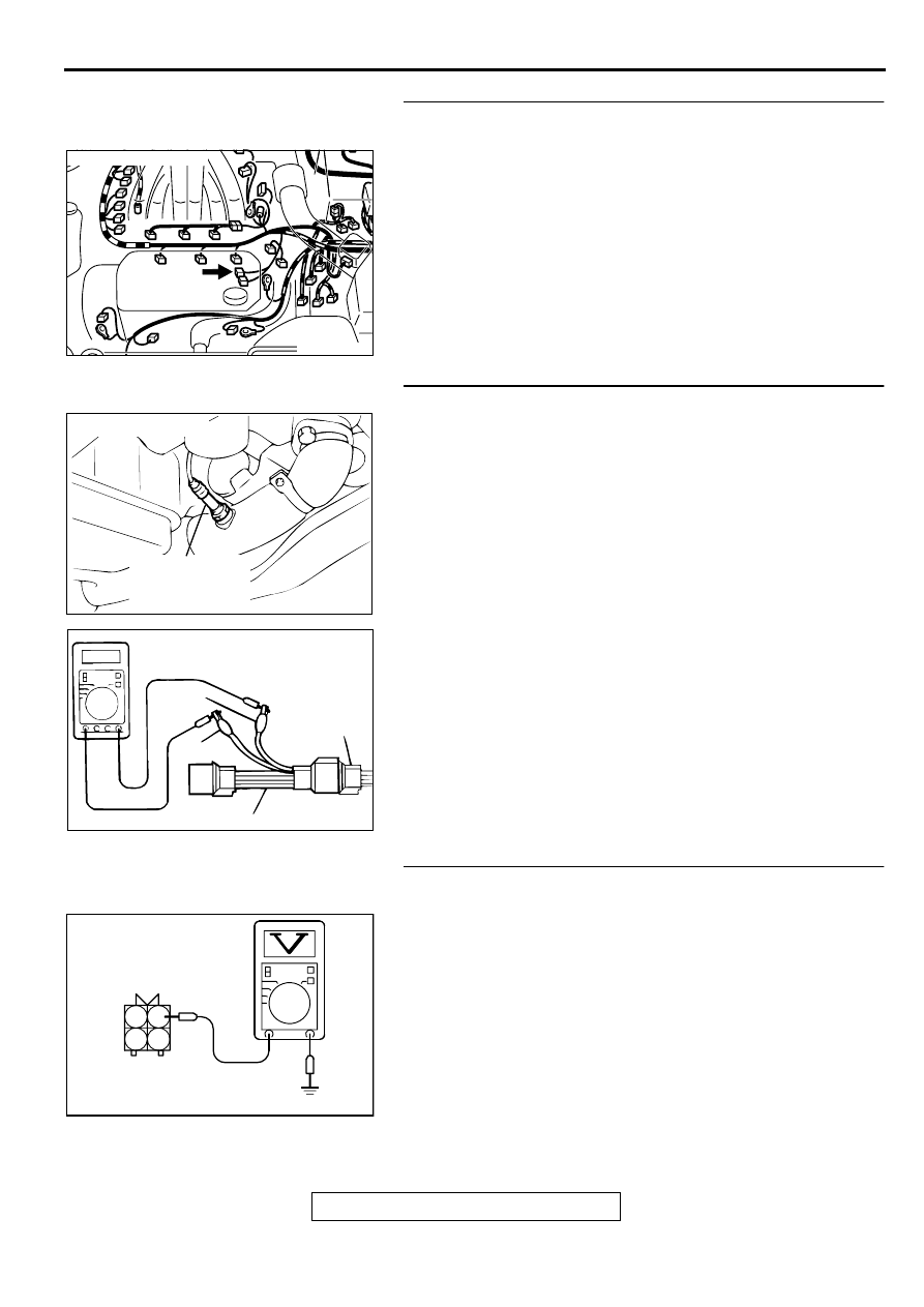
STEP 1. Check connector B-23 at the left bank heated
oxygen sensor (rear) for damage.
Q: Is the connector in good condition?
YES : Go to Step 2.
NO : Repair or replace it. Refer to GROUP 00E, Harness
Connector Inspection (
). Then go to Step 12.
STEP 2. Check the left bank heated oxygen sensor (rear).
(1) Disconnect left bank heated oxygen sensor (rear)
connector B-23 and connect test harness special tool,
MB991316, to the connector on the left bank heated oxygen
(rear) sensor side.
(2) Measure the resistance between heated oxygen sensor
connector terminal 1 (red clip) and terminal 3 (blue clip).
Standard value: 11
−
18 ohm [at 20
°
C (68
°
F)]
Q: Is the resistance normal?
YES : Go to Step 3.
NO : Replace the left bank heated oxygen sensor (rear).
Then go to Step 12.
STEP 3. Check the power supply voltage at left bank
heated oxygen sensor (rear) harness side connector B-23.
(1) Disconnect the connector B-23 and measure at the harness
side.
(2) Turn the ignition switch to the "ON" position.
(3) Measure the voltage between terminal 1 and ground.
•
Voltage should be battery positive voltage.
(4) Turn the ignition switch to the "LOCK" (OFF) position.
Q: Is the voltage normal?
YES : Go to Step 5.
NO : Go to Step 4.
AK000214
AK000214AB
CONNECTOR : B-23
ACX02488
CONNECTOR : B-23
LEFT BANK
HEATED OXYGEN
SENSOR (REAR)
AC
AKX01624 AB
MB991316
HEATED
OXYGEN
SENSOR
EQUIPMENT
SIDE
CONNECTOR
BLUE
RED
AKX01496
2
1
4
3
B-23 HARNESS
SIDE CONNECTOR
AD
Нет комментариевНе стесняйтесь поделиться с нами вашим ценным мнением.
Текст