Mitsubishi Eclipse / Eclipse Spyder (2000-2002). Service and repair manual — part 313
MULTIPORT FUEL INJECTION (MFI) DIAGNOSIS
TSB Revision
MULTIPORT FUEL INJECTION (MFI) <3.0L ENGINE>
13B-451
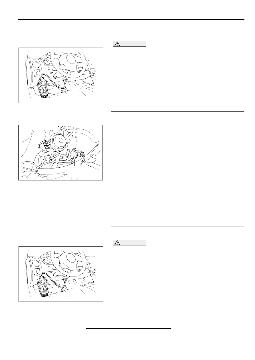
STEP 2. Using scan tool MB991502, read the diagnostic
trouble code (DTC).
CAUTION
To prevent damage to scan tool MB991502, always turn the
ignition switch to the "LOCK" (OFF) position before
connecting or disconnecting scan tool MB991502.
(1) Connect scan tool MB991502 to the data link connector.
(2) Turn the ignition switch to the "ON" position.
(3) Read the DTC.
(4) Turn the ignition switch to the "LOCK" (OFF) position.
Q: Is the DTC is output?
YES : Refer to, Diagnostic Trouble Code Chart (
NO : Go to Step 3.
STEP 3. Check the idle air control (IAC) motor operation
sound.
(1) Check that the engine coolant temperature is 20
°
C (68
°
F)
or below.
NOTE: If necessary, you can disconnect the engine coolant
temperature sensor connector and connect the harness
side of the connector to another engine coolant temperature
sensor that is at 20
°
C (68
°
F) or below.
(2) Check that the operation sound of the IAC motor can be
heard after the ignition is switched to the "ON" position (but
without starting the engine).
•
An operation sound should be heard.
(3) Turn the ignition switch to the "LOCK" (OFF) position.
Q: Did you hear the operation sound?
YES : Go to Step 4.
NO : Refer to, DTC P0506
−
Idle Control System RPM
Lower Than Expected (
), DTC P0507
−
Idle
Control System RPM Higher Than Expected (
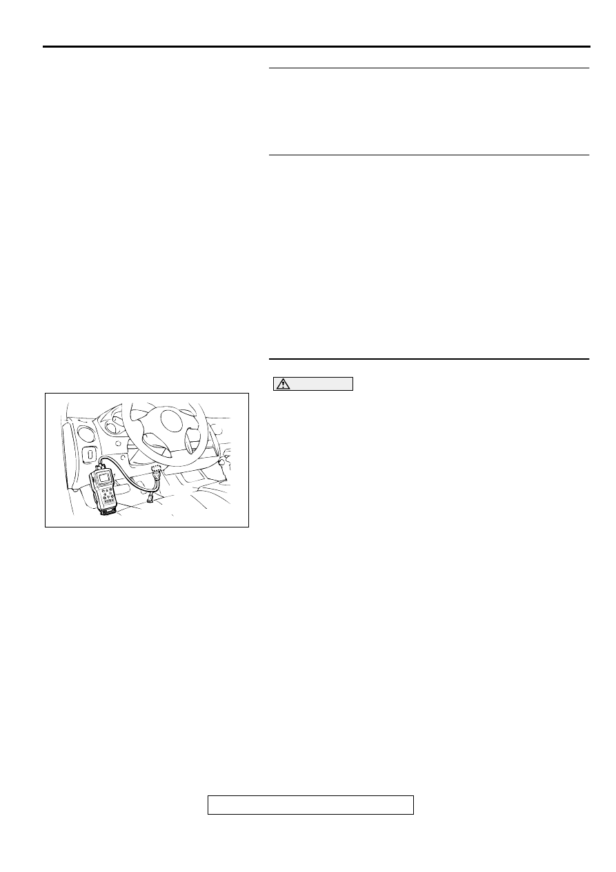
STEP 4. Using scan tool MB991502, check actuator test
items 01, 02, 03, 04, 05, 06: Injector.
CAUTION
To prevent damage to scan tool MB991502, always turn the
ignition switch to the "LOCK" (OFF) position before
connecting or disconnecting scan tool MB991502.
(1) Connect scan tool MB991502 to the data link connector.
(2) Turn the ignition switch to the "ON" position.
(3) Check following items in the actuator test. Refer to, Actuator
Test Reference Table (
).
a. Item 01, 02, 03, 04, 05, 06: Injector.
(4) Turn the ignition switch to the "LOCK" (OFF) position.
Q: Is the actuator operating properly?
YES : Go to Step 5.
NO : Refer to, DTC P0201,P0203,P0205
−
Injector Circuit
Malfunction (
),DTC P0202, P0204, P0206
−
Injector Circuit Malfunction (
AKX01177
16 PIN
MB991502
AB
ACX02523AI
IDLE AIR
CONTROL
MOTOR
CONNECTOR:B-34
AKX01177
16 PIN
MB991502
AB
MULTIPORT FUEL INJECTION (MFI) DIAGNOSIS
TSB Revision
MULTIPORT FUEL INJECTION (MFI) <3.0L ENGINE>
13B-452
STEP 5. Checking by operating the accelerator pedal
Q: Does the engine stall right after the accelerator pedal is
released?
YES : Refer to, Clean the throttle valve area (
NO : Go to Step 6.
STEP 6. Engine stall reproduction test.
Q: Is it easy to reproduce the engine stall?
YES : Go to Step 7.
NO : Check if the following signals change suddenly by
wiggling the circuit harness and connectors.
a. Crankshaft position sensor signal.
b. Volume air flow sensor signal.
c. Injector drive signal.
d. Primary and secondary ignition signal.
e. Fuel pump drive signal.
f. PCM or ECM power supply voltage.
Repair or replace. Then confirm that the malfunction
symptom is eliminated.
STEP 7. Using scan tool MB991502, check data list.
CAUTION
To prevent damage to scan tool MB991502, always turn the
ignition switch to the "LOCK" (OFF) position before
connecting or disconnecting scan tool MB991502.
(1) Connect scan tool MB991502 to the data link connector.
(2) Turn the ignition switch to the "ON" position.
(3) Check the following items in the data list. Refer to, Data List
Reference Table (
a. Item 13: Intake Air Temperature Sensor.
b. Item 25: Barometric Pressure Sensor.
c. Item 21: Engine Coolant Temperature Sensor.
d. Item 69: Right Bank Heated Oxygen Sensor (rear)
e. Item 39: Right Bank Heated Oxygen Sensor (front)
f. Item 59: Left Bank Heated Oxygen Sensor (rear)
g. Item 11: Left Bank Heated Oxygen Sensor (front)
h. Item 27: Power Steering Pressure Switch.
i. Item 28: A/C Switch.
(4) Turn the ignition switch to the "LOCK" (OFF) position.
Q: Are they operating properly?
YES : Go to Step 8.
NO : Repair or replace. Then confirm that the malfunction
symptom is eliminated.
AKX01177
16 PIN
MB991502
AB

MULTIPORT FUEL INJECTION (MFI) DIAGNOSIS
TSB Revision
MULTIPORT FUEL INJECTION (MFI) <3.0L ENGINE>
13B-453
STEP 8. Using scan tool MB991502, check actuator test.
(1) Turn the ignition switch to the "ON" position.
(2) Check the following items in the actuator test. Refer to,
Actuator Test Reference Table (
).
a. Item 10: EGR Solenoid.
(3) Turn the ignition switch to the "LOCK" (OFF) position.
Q: Is the actuator operating properly?
YES : Go to Step 9.
NO : Repair or replace. Then confirm that the malfunction
symptom is eliminated.
STEP 9. Using scan tool MB991502, check data list.
(1) Turn the ignition switch to the "ON" position.
(2) Check the following items of the data list. Refer to, Data List
Reference Table (
a. Item 39: Right Bank Heated Oxygen Sensor (front)
b. Item 11: Left Bank Heated Oxygen Sensor (front)
•
Fluctuates between 0
−
0.4 volts and 0.6
−
1.0 volts
while idling after the engine has been warmed.
(3) Turn the ignition switch to the "LOCK" (OFF) position.
Q: Is the sensor operating properly?
YES : Go to Step 12.
NO : Go to Step 10.
STEP 10. Check the fuel pressure.
Refer to, Fuel Pressure Test (
Q: Is the fuel pressure normal?
YES : Go to Step 11.
NO : Repair or replace. Then confirm that the malfunction
symptom is eliminated.
AKX01177
16 PIN
MB991502
AB
AKX01177
16 PIN
MB991502
AB

MULTIPORT FUEL INJECTION (MFI) DIAGNOSIS
TSB Revision
MULTIPORT FUEL INJECTION (MFI) <3.0L ENGINE>
13B-454
STEP 11. Using scan tool MB991502, check data list.
CAUTION
To prevent damage to scan tool MB991502, always turn the
ignition switch to the "LOCK" (OFF) position before
connecting or disconnecting scan tool MB991502.
(1) Connect scan tool MB991502 to the data link connector.
(2) Turn the ignition switch to the "ON" position.
(3) Check the following items in the data list. Refer to, Data List
Reference Table (
a. Item 45: Idle Air Control Motor Position.
(4) Turn the ignition switch to the "LOCK" (OFF) position.
Q: Is the actuator operating properly?
YES : Check the following items, and repair or replace the
defective items.
a. Vacuum leak.
•
Broken intake manifold gasket.
•
Broken air intake hose.
•
Broken vacuum hose.
•
Positive crankcase ventilation valve does
not operate.
b. Injector clogged.
Then confirm that the malfunction symptom is
eliminated.
NO : Adjusting the basic idle speed. Refer to, Basic Idle
Speed Adjustment (
STEP 12. Check the ignition timing.
Refer to GROUP 11C, On-vehicle Service
−
Ignition Timing
Check (
Q: Is the ignition timing normal?
YES : Check the following items, and repair or replace the
defective items.
a. Check the ignition coil, spark plugs, spark plug
cables.
b. Check if the injectors are clogged.
c. Check compression pressure.
d. Check if the foreign materials (water,
kerosene, etc.) got into fuel.
Then confirm that the malfunction symptom is
eliminated.
NO : Check that the crankshaft position sensor and timing
cover are in the correct position. Then confirm that the
malfunction symptom is eliminated.
INSPECTION PROCEDURE 13: The Engine Stalls when Accelerating (Pass Out).
COMMENT
•
In case such as the above, the cause is probably
misfiring due to a weak spark, or an inappropriate
air/fuel mixture when the accelerator pedal
TROUBLESHOOTING HINTS (The most likely
causes for this case:)
•
Vacuum leak.
•
Malfunction of the ignition system.
AKX01177
16 PIN
MB991502
AB
Нет комментариевНе стесняйтесь поделиться с нами вашим ценным мнением.
Текст