Mitsubishi Eclipse / Eclipse Spyder (2000-2002). Service and repair manual — part 44
PISTON AND CONNECTING ROD
TSB Revision
ENGINE OVERHAUL <2.4L ENGINE>
11B-53
>>D<< CONNECTING ROD BEARING INSTALLATION
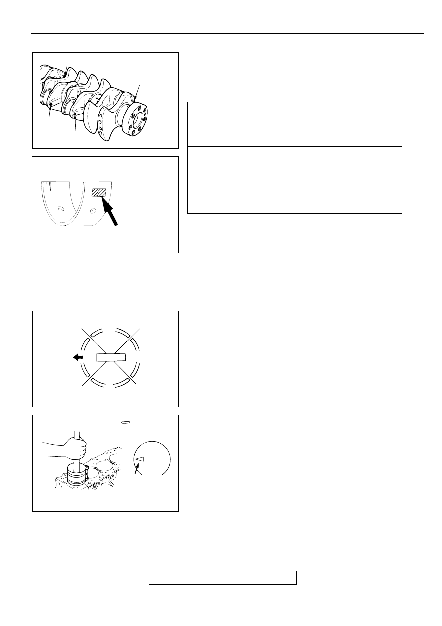
1. Measure the crankshaft pin diameter and confirm its
classification from the following table. In the case of a
crankshaft supplied as a service part, identification colors/
marks of its pins are painted /stamped at the positions
shown in the illustration.
2. If the crankshaft pin outside diameter ID color is yellow, for
example, select a bearing whose ID mark is 1 or ID color is
yellow.
If there is no ID color paint on the crankshaft, measure the
pin outside diameter and select a bearing appropriate for the
measured value.
3. Install the selected bearing in the big end and in the cap of
the connecting rod.
>>E<< PISTON AND CONNECTING ROD INSTALLATION
1. Apply engine oil on the circumference of the piston, piston
rings, and oil ring.
2. Arrange the piston ring and oil ring gaps (side rail and
spacer) as shown in the illustration.
3. Rotate the crankshaft so that crank pin is on the center of
the cylinder bore.
4. Use suitable thread protectors on the connecting rod bolts
before inserting the piston and connecting rod assembly into
the cylinder block.
Care must be taken not to nick the crank pin.
5. Insert the piston and connecting rod assembly into the
cylinder with front mark on the piston crown pointing to the
timing belt side.
6. Using a suitable piston ring compressor tool, install the
piston and connecting rod assembly into the cylinder block.
CRANKSHAFT PIN OUTSIDE
DIAMETER
CONNECTING ROD
BEARING
ID COLOR
SIZE mm (in)
ID MARK OR
COLOR
Yellow
44.995
−
45.005
(1.7715
−
1.7716)
1 or yellow
None
44.985
−
44.995
(1.7711
−
1.7714)
2
White
44.980
−
44.985
(1.7709
−
1.7714)
3 or blue
AKX00585
NO. 1
ID COLOR OF
CRANKSHAFT
PIN DIAMETER
NO. 4
NO. 2
NO. 3
AB
AKX00500
ID MARK AND COLOR OF
CONNECTING ROD BEARING SIZE
IDENTIFICATION
MARK OR COLOR
AB
AKX00456
UPPER SIDE
RAIL
NO.1
TIMING BELT
SIDE
PISTON PIN
LOWER
SIDE RAIL
NO.2 RING GAP
AND SPACER GAP
AB
AKX00440
TIMING BELT SIDE
FRONT MARK
AB
PISTON AND CONNECTING ROD
TSB Revision
ENGINE OVERHAUL <2.4L ENGINE>
11B-54
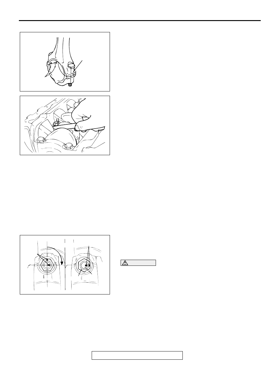
>>F<< CONNECTING ROD CAP INSTALLATION
1. Verifying the mark made during disassembly, install the
bearing cap to the connecting rod. If the connecting rod is
new with no index mark, make sure that the bearing locking
notches are on the same side as shown.
2. Make sure that the connecting rod big end side clearance
meets the specification.
Standard value: 0.10
−
0.25 mm (0.004
−
0.009 inch)
Limit: 0.4 mm (0.015 inch)
>>G<< CONNECTING ROD CAP NUT TIGHTENING
1. The connecting rod bolts should be examined before reuse.
If the bolt threads are damaged, the bolt should be replaced.
Hand-thread the nut to the full length of the bolt threads. If
the nut does not run down smoothly, the bolt should be
replaced.
2. Before installation of each nut, apply engine oil to the
threaded portion and bearing surface of the nut.
3. Loosely tighten each nut to the bolt.
4. Then tighten the nuts alternately to a torque of 20
±
2 N
⋅
m
(14
±
1 ft-lb) to install the cap properly.
5. Make a paint mark on the head of each nut.
6. Make a paint mark on the bolt end at the position 90 degree
angle to 94 degree angle from the paint mark made on the
nut in the direction of tightening the nut.
CAUTION
•
If the nut is turned less than 90 degree angle, proper
fastening performance may not be achieved. Be careful
to tighten the nut exactly 90 degree angle.
•
If the nut is overtightened (exceeding 94 degree angle),
loosen the nut completely and then retighten it by
repeating the tightening procedure from step 3.
7. Turn the nut further 90 degree angle to 94 degree angle and
make sure that the paint marks on the nut and bolt are
aligned.
AKX00535
CYLINDER NO.
NOTCHES
AB
AKX00578
AKX00450
PAINT MARK
PAINT
MARK
90˚ to 94˚
NUT
BOLT
AB
CRANKSHAFT AND CYLINDER BLOCK
TSB Revision
ENGINE OVERHAUL <2.4L ENGINE>
11B-55
C R A N K SH A FT A N D C YLIN D ER B LO C K
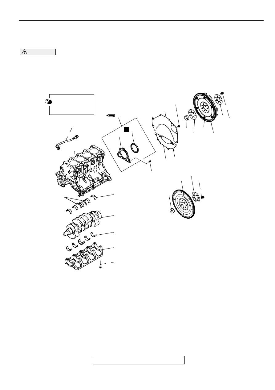
REMOVAL AND INSTALLATION
M1113008700057
CAUTION
On the flexible flywheel equipped engines, do not remove any of the bolts "A" of the flywheel shown
in the illustration. The balance of the flexible flywheel is adjusted in an assembled condition.
Removing the bolt, therefore, can cause the flexible flywheel to be out of balance giving and resulting
in damage.
AKX00512
APPLY ENGINE OIL
TO ALL MOVING
PARTS BEFORE
INSTALLATION.
11 ± 1 N·m
95 ± 9 in-lb
132 ± 5 N·m
98 ± 4 ft-lb
23 ± 2 N·m
17 ± 1 ft-lb
8.8 ± 1 N·m
78 ± 9 in-lb
11 ± 1 N·m
95 ± 9 in-lb
132 ± 5 N·m
98 ± 4 ft-lb
25 ± 2 N·m
18 ± 1 ft-lb
+ 90˚
10
1
12
2
13
5
A
14
21
4
3
22
11
7
8
6
9
20
19
18
17
16
15
N
AB
REMOVAL STEPS
1. FLYWHEEL BOLT <M/T>
2. ADAPTER PLATE <M/T>
3 FLYWHEEL <M/T>
4. ADAPTER PLATE <M/T>
5. CRANKSHAFT BUSHING <M/T>
6. DRIVE PLATE BOLT <A/T>
7. ADAPTER PLATE <A/T>
8. DRIVE PLATE <A/T>
9. CRANKSHAFT BUSHING <A/T>
10.REAR PLATE
11. BELL HOUSING COVER
>>E<<
12.OIL SEAL CASE ASSEMBLY
>>D<<
13.OIL SEAL
14.OIL SEAL CASE
>>C<<
15.BEARING CAP BOLT
>>C<<
16.BEARING CAP
>>B<<
17.CRANKSHAFT BEARING (LOWER)
18.CRANKSHAFT
>>B<<
19.CRANKSHAFT BEARING (UPPER)
>>A<<
20.CRANKSHAFT THRUST BEARING
21.KNOCK SENSOR
22.CYLINDER BLOCK
REMOVAL STEPS (Continued)
CRANKSHAFT AND CYLINDER BLOCK
TSB Revision
ENGINE OVERHAUL <2.4L ENGINE>
11B-56
Required Special Tools:
MB990938: Handle
MD998776: Crankshaft Rear Oil Seal Installer
INSTALLATION SERVICE POINTS
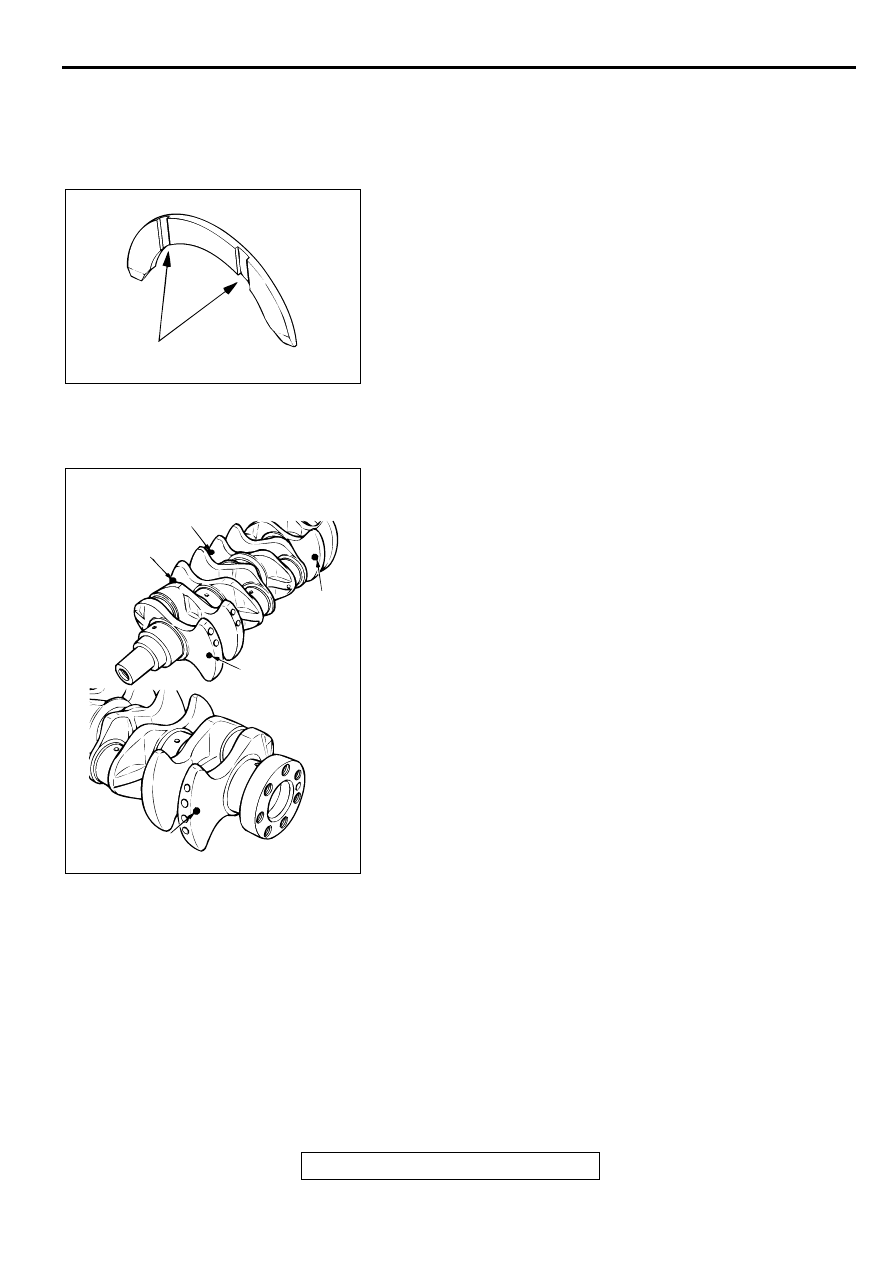
>>A<< CRANKSHAFT THRUST BEARING INSTALLATION
1. Install the two thrust bearings in the number 3 bearing bore
in the cylinder block. For easier installation, apply engine oil
to the bearings; this will help hold them in position.
2. The thrust bearings must be installed with their groove side
toward the crankshaft web.
>>B<< CRANKSHAFT BEARING INSTALLATION
When bearing replacement is required, select and install the
correct bearing by the following procedure.
1. Measure the crankshaft journal diameter and confirm its
classification from the following table. In the case of a
crankshaft supplied as a service part, identification colors/
marks of its journals are painted/stamped at the positions
shown in the illustration.
AKX00497
GROOVE
AB
AKX00587
NO.5
ID COLOR OF CRANKSHAFT
JOURNAL
NO.3
NO.2
NO.4
NO.1
AB
Нет комментариевНе стесняйтесь поделиться с нами вашим ценным мнением.
Текст