Mitsubishi Eclipse / Eclipse Spyder (2000-2002). Service and repair manual — part 149
MULTIPORT FUEL INJECTION (MFI) DIAGNOSIS
TSB Revision
MULTIPORT FUEL INJECTION (MFI) <2.4L ENGINE>
13A-295
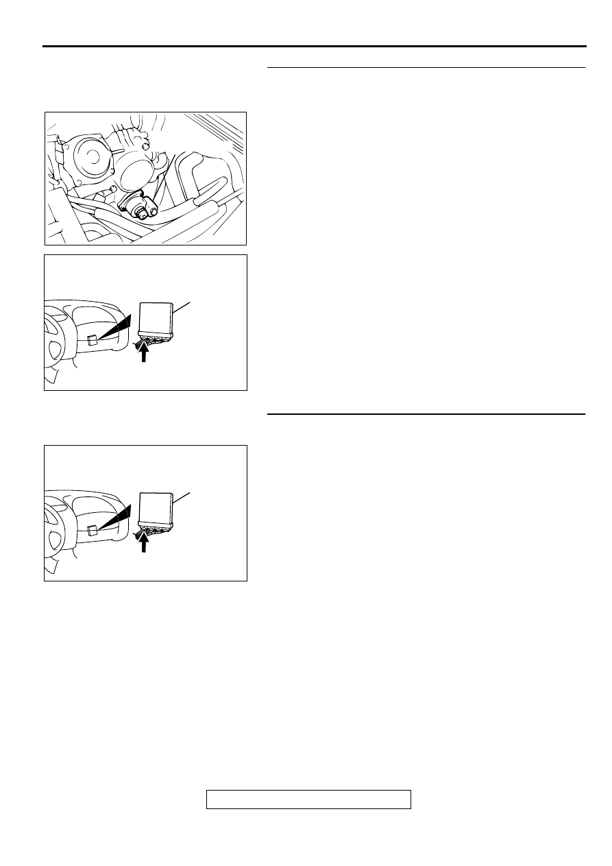
STEP 9. Check for open circuit and short circuit to ground
between idle air control motor connector B-34 and ECM
connector C-49 <M/T> or PCM connector C-50 <A/T>.
a. Idle air control motor connector B-34 terminal 1 and ECM
connector C-49 terminal 4 <M/T> or PCM connector C-50
terminal 14 <A/T>.
b. Idle air control motor connector B-34 terminal 3 and ECM
connector C-49 terminal 17 <M/T> or PCM connector C-50
terminal 28 <A/T>.
c. Idle air control motor connector B-34 terminal 4 and ECM
connector C-49 terminal 5 <M/T> or PCM connector C-50
terminal 15 <A/T>.
d. Idle air control motor connector B-34 terminal 6 and ECM
connector C-49 terminal 18 <M/T> or PCM connector C-50
terminal 29 <A/T>.
Q: Is the harness wire in good condition?
YES : Replace the ECM or PCM. Then go to Step 14.
NO : Repair it. Then go to Step 14.
STEP 10. Check connector C-49 at ECM <M/T> or
connector C-50 at PCM <A/T> for damage.
Q: Is the connector in good condition?
YES : Go to Step 11.
NO : Repair or replace it. Refer to GROUP 00E, Harness
Connector Inspection (
). Then go to Step 14.
ACX02519 AI
IDLE AIR
CONTROL MOTOR
CONNECTOR:B-34
AK000280
C-49,C-50
ECM<M/T>
OR
PCM<A/T>
CONNECTORS:C-49<M/T>,C-50<A/T>
BC
AK000280
C-49,C-50
ECM<M/T>
OR
PCM<A/T>
CONNECTORS:C-49<M/T>,C-50<A/T>
BC
MULTIPORT FUEL INJECTION (MFI) DIAGNOSIS
TSB Revision
MULTIPORT FUEL INJECTION (MFI) <2.4L ENGINE>
13A-296
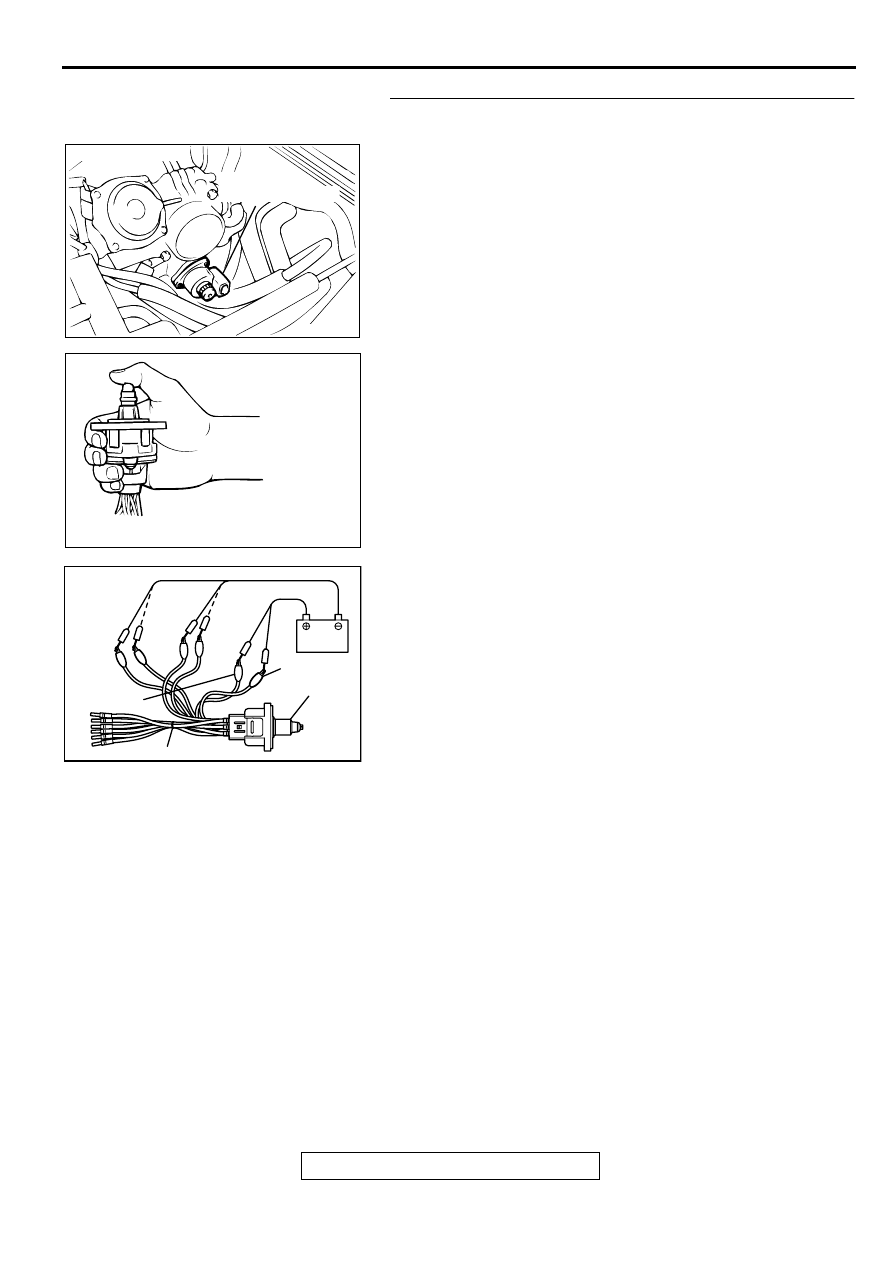
STEP 11. Check the idle air control motor operation using
special tool MB991709.
(1) Remove the idle air control motor.
(2) Connect special tool MB991709 to the idle air control motor.
(All terminals should be connected.)
(3) Use the jumper wires to connect terminal 2 of the idle air
control motor connector to the battery (+) terminal.
(4) Check the ensure that the motor operates when the
terminals 1 and 3 of the idle air control motor connector are
respectively connected to the battery (-) terminal using a
jumper wire.
•
Vibration should be present at each application of
voltage to test clip combination.
(5) Then. Use jumper wires to connect the terminal 5 of the idle
air control motor connector to the battery (+) terminal.
(6) Check the ensure that the motor operates when the
terminals 4 and 6 of the idle air control motor connector are
respectively connected to the battery (-) terminal using a
jumper wire.
•
Vibration should be present at each application of
voltage to test clip combination.
(7) Install the idle air control motor. Refer to, Throttle Body
−
Disassembly and Assembly (
).
Q: Is the idle air control motor operating properly?
YES : Go to Step 12.
NO : Replace the idle air control motor. Then go to Step 14.
ACX02519 AI
IDLE AIR
CONTROL MOTOR
CONNECTOR:B-34
AKX01626
AKX01627AB
TERMINAL 2
IAC MOTOR
TERMINAL 5
MB991709
MULTIPORT FUEL INJECTION (MFI) DIAGNOSIS
TSB Revision
MULTIPORT FUEL INJECTION (MFI) <2.4L ENGINE>
13A-297
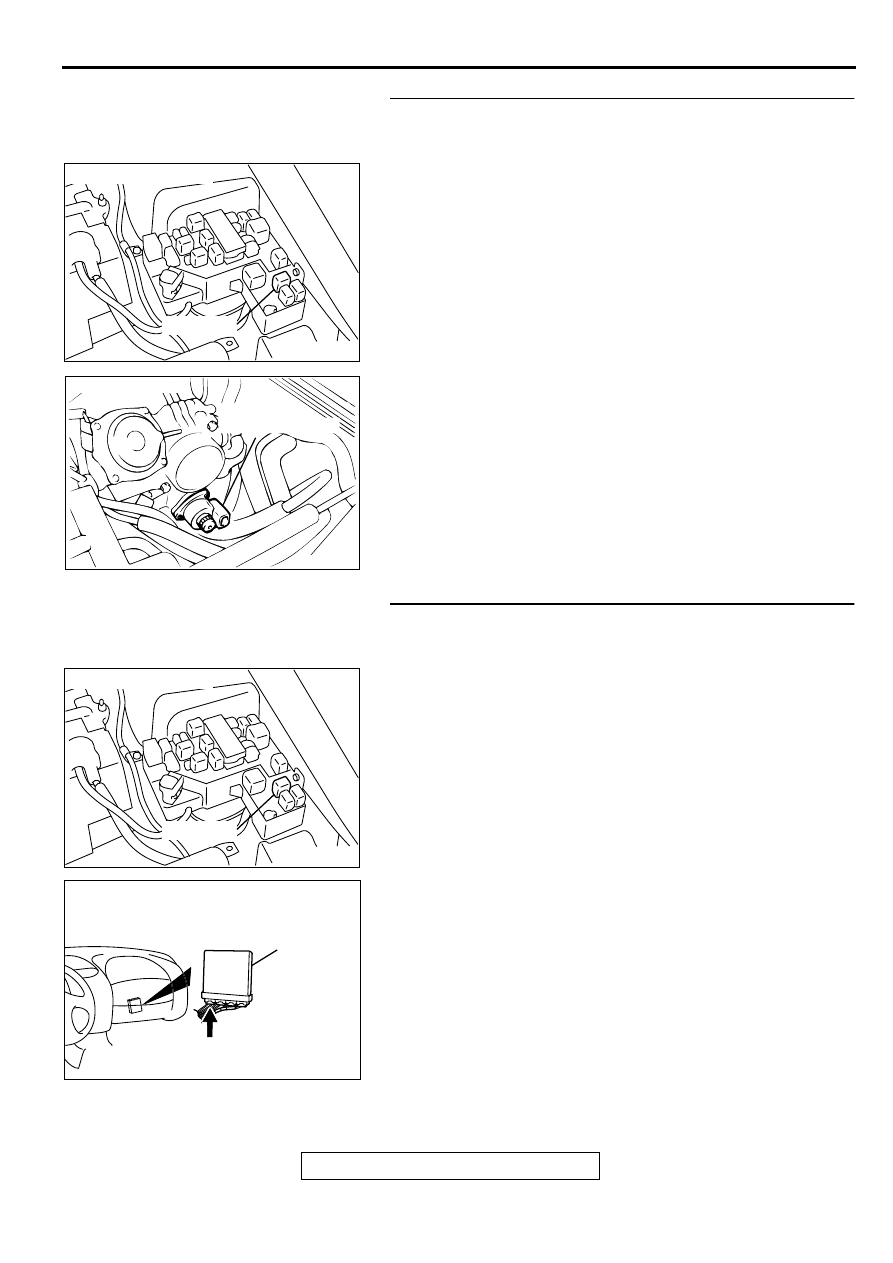
STEP 12. Check for harness damage between MFI relay
connector A-21X terminal 1 and idle air control motor
connector B-34 terminal 2, 5.
Q: Is the harness wire in good condition?
YES : Go to Step 13.
NO : Repair it. Then go to Step 14.
STEP 13. Check for harness damage between idle air
control motor connector B-34 and ECM connector C-49
<M/T> or PCM connector C-50 <A/T>.
a. Idle air control motor connector B-34 terminal 1 and ECM
connector C-49 terminal 4 <M/T> or PCM connector C-50
terminal 14 <A/T>.
b. Idle air control motor connector B-34 terminal 3 and ECM
connector C-49 terminal 17 <M/T> or PCM connector C-50
terminal 28 <A/T>.
c. Idle air control motor connector B-34 terminal 4 and ECM
connector C-49 terminal 5 <M/T> or PCM connector C-50
terminal 15 <A/T>.
d. Idle air control motor connector B-34 terminal 6 and ECM
connector C-49 terminal 18 <M/T> or PCM connector C-50
terminal 29 <A/T>.
Q: Is the harness wire in good condition?
YES : Replace the ECM or PCM. Then go to Step 14.
NO : Repair it. Then go to Step 14.
AK000226
AK000226AB
CONNECTOR : A-21X
MFI RELAY
ACX02519 AI
IDLE AIR
CONTROL MOTOR
CONNECTOR:B-34
AK000226
AK000226AB
CONNECTOR : A-21X
MFI RELAY
AK000280
C-49,C-50
ECM<M/T>
OR
PCM<A/T>
CONNECTORS:C-49<M/T>,C-50<A/T>
BC
MULTIPORT FUEL INJECTION (MFI) DIAGNOSIS
TSB Revision
MULTIPORT FUEL INJECTION (MFI) <2.4L ENGINE>
13A-298
STEP 14. Test the OBD-II drive cycle.
(1) Carry out a test drive with the drive cycle pattern. Refer to,
Procedure 6
−
Other Monitor (
).
(2) Check the diagnostic trouble code (DTC).
Q: Is the DTC P0506 is output?
YES : Retry the troubleshooting.
NO : The inspection is complete.
Нет комментариевНе стесняйтесь поделиться с нами вашим ценным мнением.
Текст