Mitsubishi Eclipse / Eclipse Spyder (2000-2002). Service and repair manual — part 150
MULTIPORT FUEL INJECTION (MFI) DIAGNOSIS
TSB Revision
MULTIPORT FUEL INJECTION (MFI) <2.4L ENGINE>
13A-299
DTC P0507: Idle Control System RPM Higher Than Expected
AK000669
1 2
3 4
6
17
8
15
9
18
7
20
16
2
10
13
12
23 24 25 26
11
21
3
1
14
4
12
11
16
5 6
7 8
21
13
27
14
28
15
29
17
30
18
31
19
32
20
33
22
34
23
35
1
24
3
26
9
2
25
10
19
5
4
22
1 2
4 5 6
3
RED-
WHITE
RED-
WHITE
RED-
WHITE
RED
RED
RED
GREEN-BLA
CK
GREEN-RED
GREEN-WHITE
BLA
CK-YELLO
W
C-49<M/T>
(MU803773)
C-50<A/T>
(MU803784)
B-34
IDLE AIR
CONTROL(IAC)
MOTOR
A-21X
BATTERY
MFI
RELAY
1
1
2
2
3
3
4
4
5
6
ENGINE CONTROL
MODULE(ECM)<M/T>
OR
POWERTRAIN CONTROL
MODULE(PCM)<A/T>
4<M/T>
14<A/T>
17<M/T>
28<A/T>
5<M/T>
15<A/T>
18<M/T>
29<A/T>
MULTIPORT FUEL INJECTION (MFI) DIAGNOSIS
TSB Revision
MULTIPORT FUEL INJECTION (MFI) <2.4L ENGINE>
13A-300
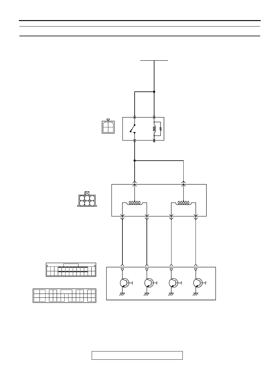
CIRCUIT OPERATION
•
The idle air control motor power is supplied from
the MFI relay (terminal 1).
•
The ECM (terminals 4, 5, 17, 18) <M/T> or PCM
(terminals 14, 15, 28, 29) <A/T> drives the
stepper motor by sequentially turning "ON" the
power transistors in the ECM <M/T> or PCM <A/
T> and providing ground to the idle air control
motor (terminals 1, 3, 4, 6).
TECHNICAL DESCRIPTION
•
The amount of air taken in during idling is
regulated by the opening and closing of the servo
valve located in the air passage that bypasses
the throttle body.
•
If there is a malfunction of the IAC system, the
actual engine speed will not be identical to the
target engine speed.
•
The ECM <M/T> or PCM <A/T> checks the
difference between the actual engine speed and
the target engine speed.
DTC SET CONDITIONS
Check Conditions
•
Vehicle speed has reached 1.5 km/h (0.93 mph)
or more at least once.
•
Under the closed loop idle speed control.
Judgment Criteria
•
Actual idle speed has continued to be higher than
the target idle speed by 300 r/min or more for 12
seconds.
Check Conditions
•
Vehicle speed has reached 1.5 km/h (0.93 mph)
or more at least once.
•
Under the closed loop idle speed control.
•
The highest atmospheric temperature at the last
drive is 45
°
C (113
°
F) or less.
•
Engine coolant temperature is higher than 82
°
C
(180
°
F).
•
Battery positive voltage is higher than 10 volts.
•
Barometric pressure is higher than 76 kPa (11
psi).
•
Intake air temperature is higher than -10
°
C (14
°
F).
Judgment Criteria
•
Actual idle speed has continued to be higher than
the target idle speed by 200 r/min or more for 12
seconds.
TROUBLESHOOTING HINTS (The most likely
causes for this code to be set are:)
•
Idle air control motor failed.
•
Open or shorted idle air control motor circuit, or
loose connector.
•
ECM failed. <M/T>
•
PCM failed. <A/T>
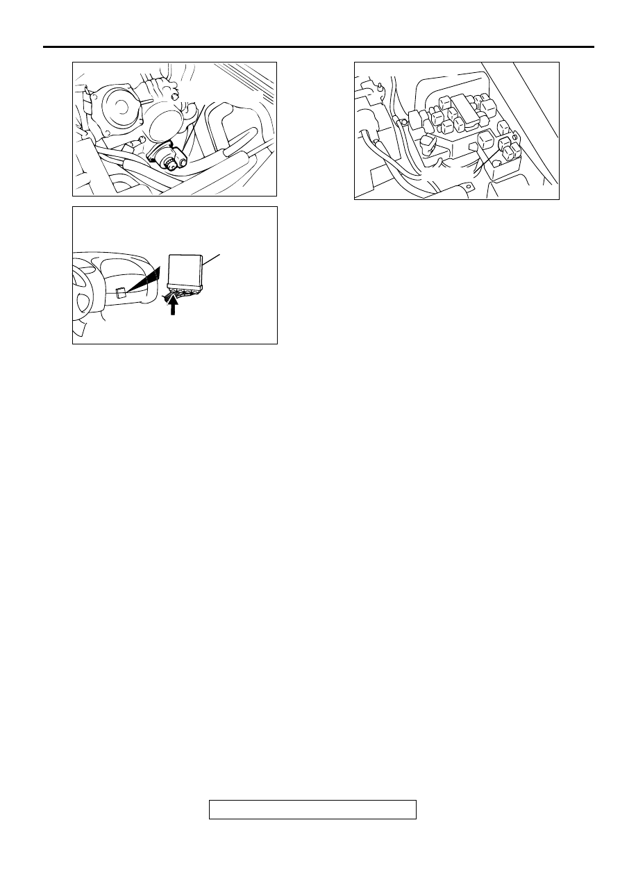
ACX02519 AI
IDLE AIR
CONTROL MOTOR
CONNECTOR:B-34
AK000280
C-49,C-50
ECM<M/T>
OR
PCM<A/T>
CONNECTORS:C-49<M/T>,C-50<A/T>
BC
AK000226
AK000226AB
CONNECTOR : A-21X
MFI RELAY
MULTIPORT FUEL INJECTION (MFI) DIAGNOSIS
TSB Revision
MULTIPORT FUEL INJECTION (MFI) <2.4L ENGINE>
13A-301
DIAGNOSIS
Required Special Tools
MB991502: Scan Tool (MUT-II)
MB991709: Test harness
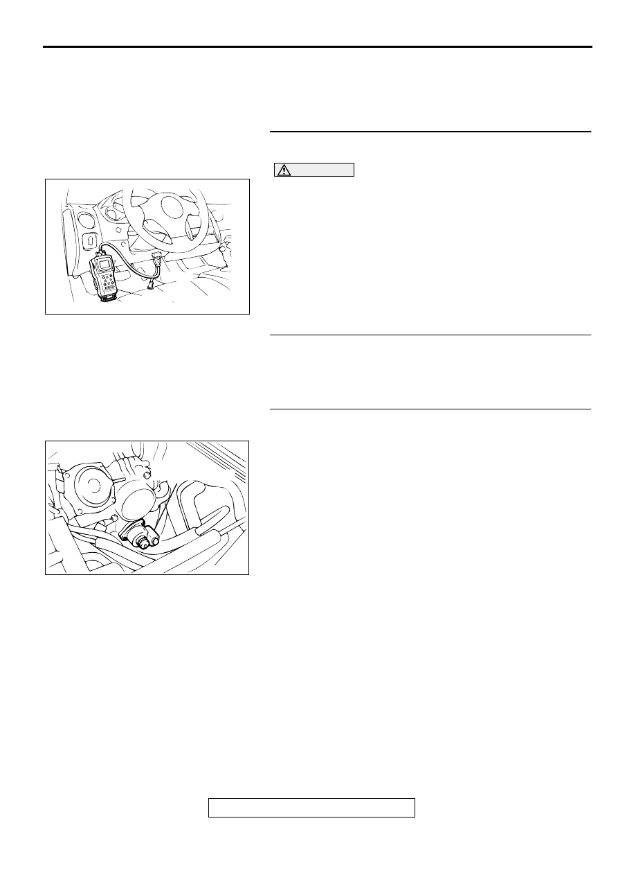
STEP 1. Using scan tool MB991502, read the diagnostic
trouble code (DTC).
CAUTION
To prevent damage to scan tool MB991502, always turn the
ignition switch to the "LOCK" (OFF) position before
connecting or disconnecting scan tool MB991502.
(1) Connect scan tool MB991502 to the data link connector.
(2) Turn the ignition switch to the "ON" position.
(3) Set scan tool MB991502, read the DTC.
(4) Turn the ignition switch to the "LOCK" (OFF) position.
Q: Is the diagnostic trouble code other than P0507 output?
YES : Refer to, Diagnostic Trouble Code Chart (
NO : Go to Step 2.
STEP 2. Check the intake system vacuum leak.
Q: Are there any abnormalities?
YES : Go to Step 3.
NO : Repair or replace it. Then go to Step 14.
STEP 3. Check connector B-34 at idle air control motor for
damage.
Q: Is the connector in good condition?
YES : Go to Step 4.
NO : Repair or replace it. Refer to GROUP 00E, Harness
Connector Inspection (
). Then go to Step 14.
AKX01177
16 PIN
MB991502
AB
ACX02519 AI
IDLE AIR
CONTROL MOTOR
CONNECTOR:B-34
MULTIPORT FUEL INJECTION (MFI) DIAGNOSIS
TSB Revision
MULTIPORT FUEL INJECTION (MFI) <2.4L ENGINE>
13A-302
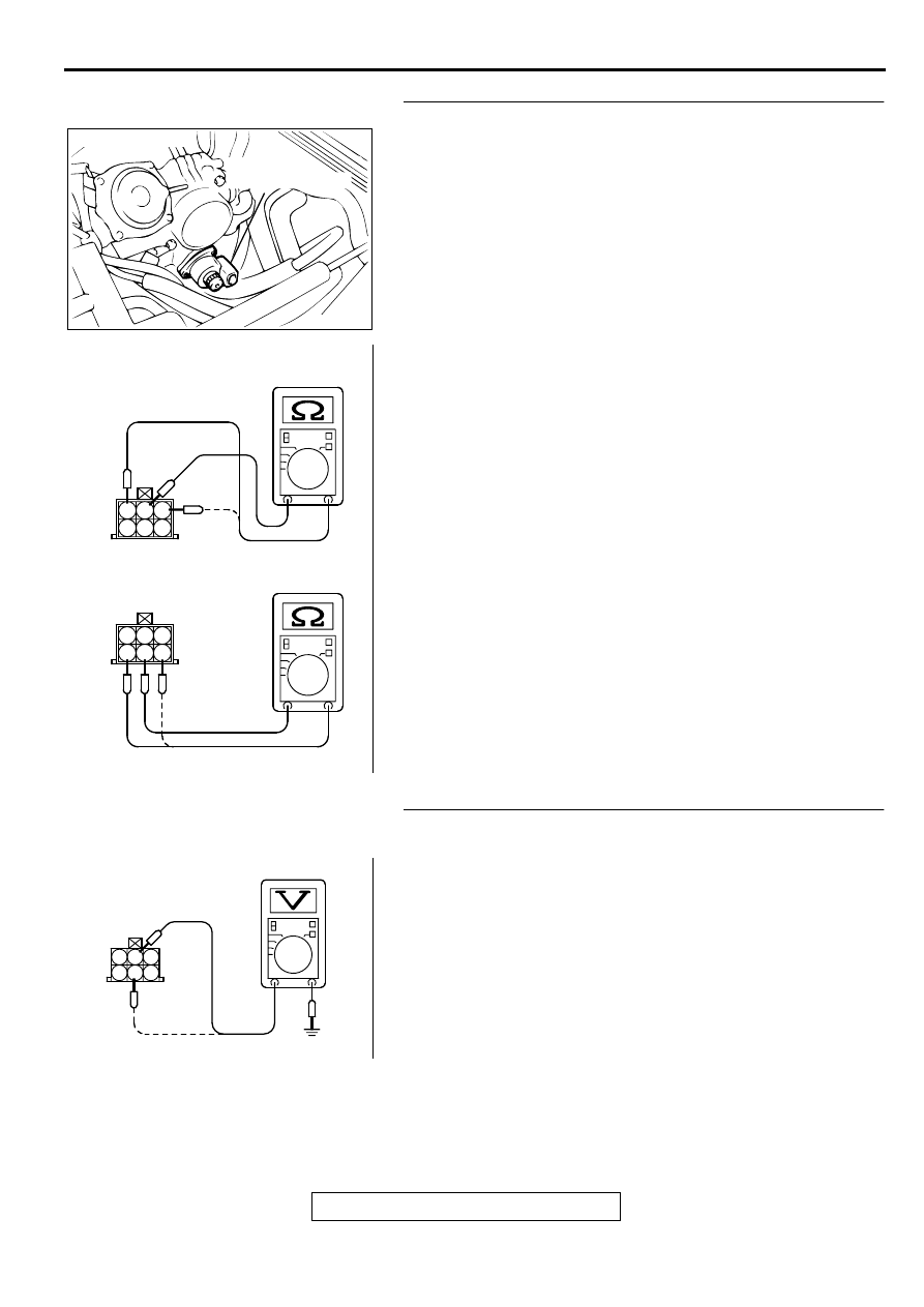
STEP 4. Check the idle air control motor coil resistance.
(1) Disconnect the idle air control motor connector B-34.
(2) Measure the resistance between idle air control motor
connector terminal 2 and either terminal 1 or terminal 3.
Standard value: 28
−
33 ohm [at 20
°
C (68
°
F)]
(3) Measure the resistance between idle air control motor
connector terminal 5 and either terminal 4 or terminal 6.
Standard value: 28
−
33 ohm [at 20
°
C (68
°
F)]
Q: Is the resistance normal?
YES : Go to Step 5.
NO : Replace the idle air control motor. Then go to Step 14.
STEP 5. Check the power supply voltage at idle air control
motor harness side connector B-34.
(1) Disconnect the connector B-34 and measure at the harness
side.
(2) Turn the ignition switch to the "ON" position.
(3) Measure the voltage between terminal 2, 5 and ground.
•
Voltage should be battery positive voltage.
(4) Turn the ignition switch to the "LOCK" (OFF) position.
Q: Is the voltage normal?
YES : Go to Step 7.
NO : Go to Step 6.
ACX02519 AI
IDLE AIR
CONTROL MOTOR
CONNECTOR:B-34
AKX01561
1 2 3
4 5 6
1 2 3
4 5 6
AB
AKX01428
1
2
3
5 4
6
B-34 HARNESS
SIDE CONNECTOR
AF
Нет комментариевНе стесняйтесь поделиться с нами вашим ценным мнением.
Текст