Mitsubishi Eclipse / Eclipse Spyder (2000-2002). Service and repair manual — part 24
ENGINE ASSEMBLY
TSB Revision
ENGINE MECHANICAL <2.4L ENGINE>
11A-13
AC001692
1
19
4.8 ± 1.0 N·m
44 ± 8 in-lb
20
17
16
2
3
18
4
14
15
9
8
7
6
5
10
11
12
19
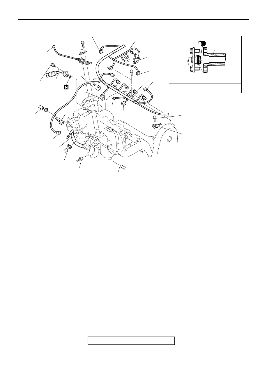
O-RING
FUEL RAIL
ENGINE OIL
12 ± 2 N·m
100 ± 22 in-lb
21
AB
13
REMOVAL STEPS
1.
ACCELERATOR CABLE
CONNECTION
2.
PURGE HOSE CONNECTION
3.
BRAKE BOOSTER VACUUM
HOSE CONNECTION
4.
VACUUM HOSE CONNECTION
5.
IGNITION COIL CONNECTOR
6.
INJECTOR CONNECTOR
7.
IGNITION FAILURE SENSOR
CONNECTOR
8.
MANIFOLD DIFFERENTIAL
PRESSURE SENSOR
CONNECTOR
9.
THROTTLE POSITION SENSOR
CONNECTOR
10. HEATED OXYGEN SENSOR
(FRONT) CONNECTOR
11. CAPACITOR CONNECTOR
12. ENGINE COOLANT
TEMPERATURE SENSOR
CONNECTOR
13. CAMSHAFT POSITION
SENSOR CONNECTOR
14. KNOCK SENSOR CONNECTOR
15. ENGINE COOLANT
TEMPERATURE GAUGE UNIT
CONNECTOR
16. IDLE AIR CONTROL MOTOR
CONNECTOR
17. EVAPORATIVE EMISSION
PURGE SOLENOID VALVE
CONNECTOR
18. EGR SOLENOID VALVE
CONNECTOR
>>D<<
19. HIGH-PRESSURE FUEL HOSE
CONNECTION
20. FUEL RETURN HOSE
CONNECTION
21. PRESSURE HOSE
CONNECTION
REMOVAL STEPS (Continued)
ENGINE ASSEMBLY
TSB Revision
ENGINE MECHANICAL <2.4L ENGINE>
11A-14
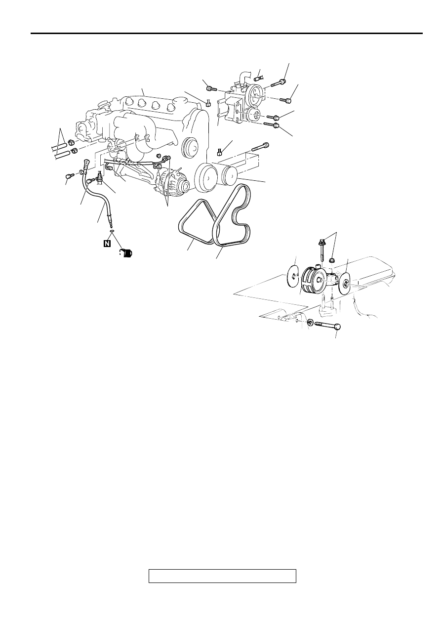
Required Special Tools:
•
MB991453: Engine Hanger Assembly
•
MZ203827: Engine Lifter
AC001694
24
14 ± 1 N·m
117 ± 13 in-lb
12 ± 2 N·m
100 ± 22 in-lb
22
(ENGINE OIL)
26
23
25
28
27
33
29
29 ± 3 N·m
21 ± 3 ft-lb
36
30
49 ± 10 N·m
36 ± 7 ft-lb
29 ± 3 N·m
21 ± 3 ft-lb
11 ± 1 N·m
96 ± 8 in-lb
49 ± 10 N·m
36 ± 7 ft-lb
31
32
86 ± 12 N·m
64 ± 8 ft-lb
35
35
34
81 ± 12 N·m*
60 ± 9 ft-lb*
AB
22. OIL DIPSTICK AND DIPSTICK
GUIDE
23. PRESSURE HOSE CONNECTION
24. HEATER HOSE CONNECTION
25. GENERATOR CONNECTOR
26. OIL PRESSURE SWITCH
CONNECTOR
27. DRIVE BELT (POWER STEERING
OIL PUMP AND A/C
COMPRESSOR)
28. DRIVE BELT (GENERATOR)
29. CRANKSHAFT POSITION SENSOR
CONNECTOR
30. POWER STEERING PRESSURE
SWITCH CONNECTOR
<<A>>
31. POWER STEERING OIL PUMP AND
BRACKET ASSEMBLY
32. A/C COMPRESSOR ASSEMBLY
CONNECTOR
<<B>>
33. A/C COMPRESSOR
<<C>>
•
TRANSAXLE ASSEMBLY
<<D>> >>C<<
34. ENGINE MOUNT BRACKET
>>B<<
35. ENGINE MOUNT STOPPER
<<E>> >>A<<
36. ENGINE ASSEMBLY
ENGINE ASSEMBLY
TSB Revision
ENGINE MECHANICAL <2.4L ENGINE>
11A-15
REMOVAL SERVICE POINTS
<<A>> POWER STEERING OIL PUMP AND BRACKET
ASSEMBLY REMOVAL
Remove the power steering oil pump and bracket assembly
from the engine with the hose attached.
NOTE: Place the removed power steering oil pump in a place
where it will not be a hindrance when removing and installing
the engine assembly, and secure it with a cord or wire.
<<B>> A/C COMPRESSOR REMOVAL
Remove the compressor from the compressor bracket with the
hose still attached.
NOTE: Place the removed A/C compressor where it will not be
a hindrance when removing and installing the engine assembly,
and secure it with a cord or wire.
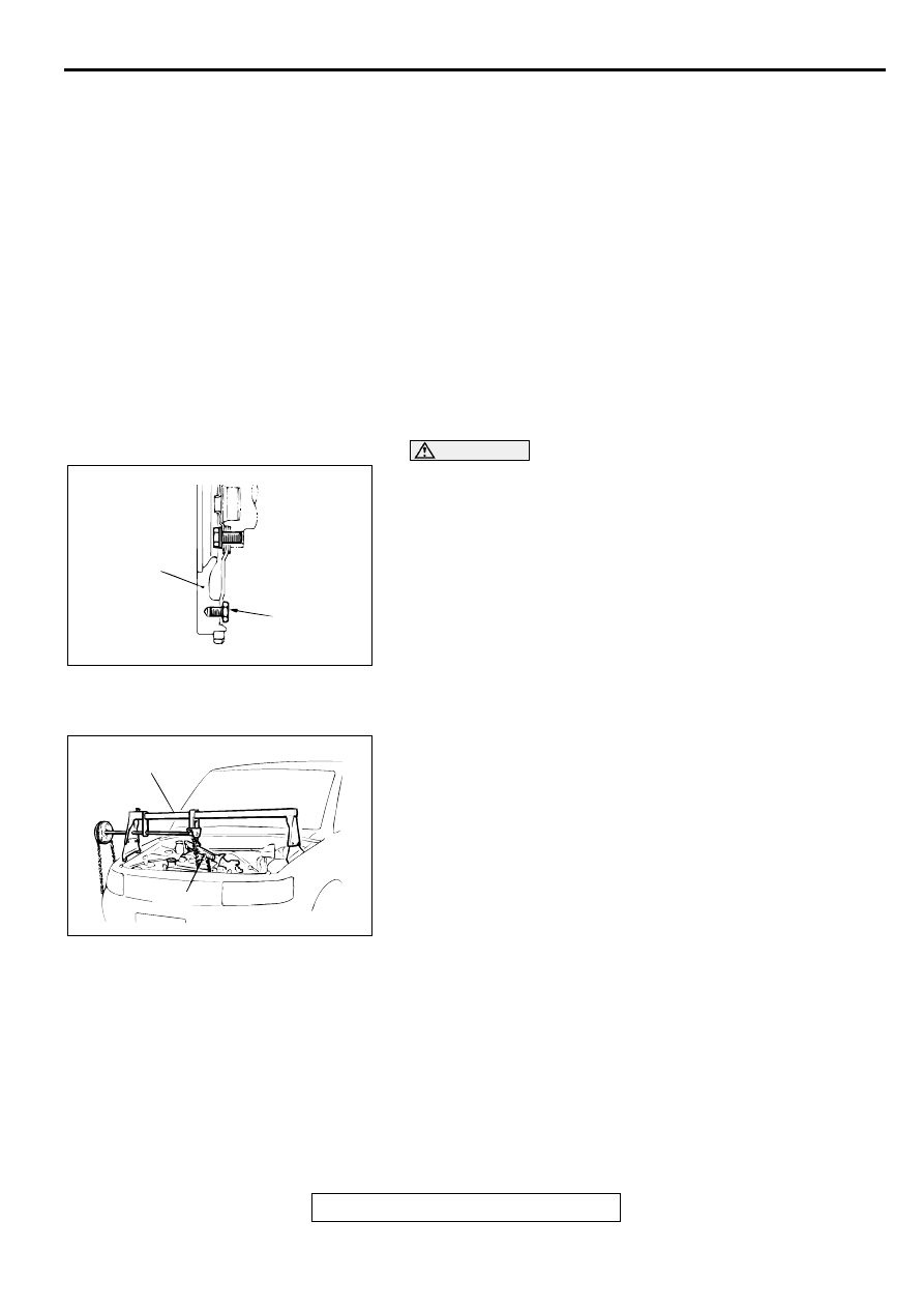
<<C>> TRANSAXLE ASSEMBLY REMOVAL
CAUTION
Do not remove the flywheel mounting bolt shown by the
arrow. If this bolt Is removed, the flywheel will become out
of balance and damaged.
<M/T>: Refer to GROUP 22A, Transaxle Assembly
<A/T>: Refer to GROUP 23A, Transaxle Assembly
.
<<D>> ENGINE MOUNT BRACKET REMOVAL
1. Support the engine with a garage jack.
2. Remove special tools MB991453 and MZ203827 which was
attached when the transaxle assembly was removed.
3. Hold the engine assembly with a chain block or similar tool.
4. Place a garage jack against the engine oil pan with a piece
of wood in between, jack up the engine so that the weight of
the engine is no longer being applied to the engine mount
bracket, and then remove the engine mount bracket.
<<E>> ENGINE ASSEMBLY REMOVAL
After checking that all cables, hoses and harness connectors,
etc., are disconnected from the engine, lift the chain block
slowly to remove the engine assembly upward from the engine
compartment.
INSTALLATION SERVICE POINTS
>>A<< ENGINE ASSEMBLY INSTALLATION
Install the engine assembly, checking that the cables, hoses,
and harness connectors are not clamped.
AC000126
FLYWHEEL
BOLT
AB
<M/T>
AC000127
MZ203827
MB991453
AB
ENGINE ASSEMBLY
TSB Revision
ENGINE MECHANICAL <2.4L ENGINE>
11A-16
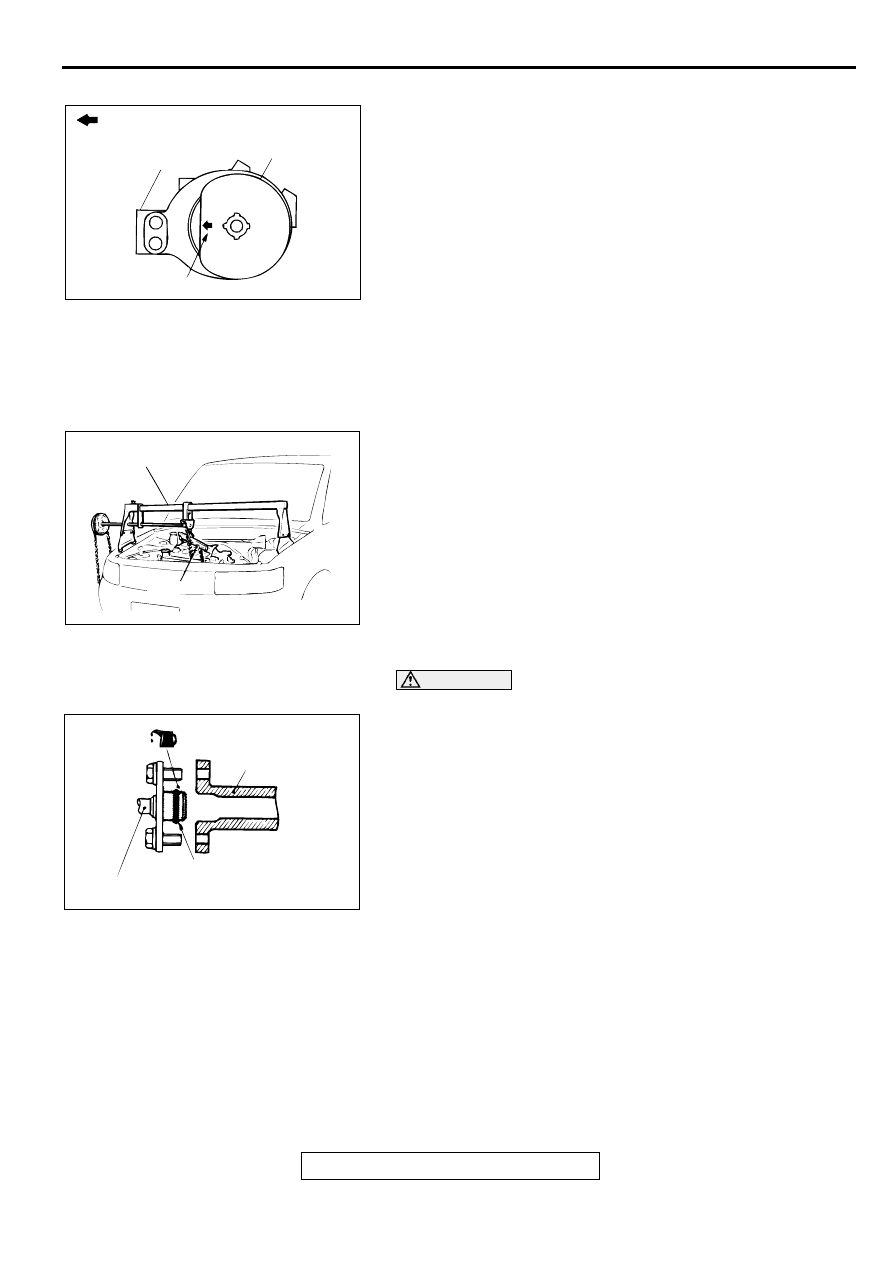
>>B<< ENGINE MOUNT STOPPER INSTALLATION
Clamp the engine mount stopper so that the arrow points in the
direction as shown in the diagram.
>>C<< ENGINE MOUNT BRACKET INSTALLATION
1. Place a garage jack against the engine oil pan with a piece
of wood in between, and install the engine mount bracket
while adjusting the position of the engine.
2. Support the engine with the garage jack.
3. Remove the chain block and support the engine assembly
with special tools MB991453 and MZ203827.
>>D<< HIGH-PRESSURE FUEL HOSE INSTALLATION
CAUTION
Do not allow any engine oil to enter the fuel rail.
1. Apply a small amount of new engine oil to the O-ring.
2. While turning the high-pressure fuel hose to the right and
left, install it to the fuel rail, while being careful not to
damage the O-ring. After installing, check that the hose
turns smoothly.
3. If the hose does not turn smoothly, the O-ring is probably
being clamped. Disconnect the high-pressure fuel hose and
check the O-ring for damage. Replace if necessary.
4. Re-insert the fuel rail and confirm the hose turns smoothly.
AC000128
ENGINE SIDE
ENGINE MOUNT
BRACKET
ENGINE MOUNT
STOPPER
ARROW
AB
AC000127
MZ203827
MB991453
AB
AC000129 AB
FUEL RAIL
HIGH-PRESSURE
FUEL HOSE
O-RING
Нет комментариевНе стесняйтесь поделиться с нами вашим ценным мнением.
Текст