Mitsubishi Eclipse / Eclipse Spyder (2000-2002). Service and repair manual — part 25
CAMSHAFT AND CAMSHAFT OIL SEAL
TSB Revision
ENGINE MECHANICAL <2.4L ENGINE>
11A-17
C A M SH A FT A N D C A M SH A FT O IL SEA L
REMOVAL AND INSTALLATION
M1112001900154
Required Special Tools:
•
MB990767: End Yoke Holder
•
MB998713: Crankshaft Oil Seal Installer
•
MD998443: Auto-lash Adjuster Holder
•
MD998719: Crankshaft Pulley Holder Pin
Pre-removal and Post-installation Operation
•
Air Cleaner Removal and Installation (Refer to GROUP
15, Air Cleaner
•
Timing Belt Removal and Installation (Refer to
AC000130
2
1
9.8 ± 2.0 N·m
87 ± 17 in-lb
3.4 ± 0.5 N·m
31 ± 4 in-lb
5
4
3
6
7
13
10
N
N
11
12
31 ± 3 N·m
23 ± 2 ft-lb
88 ± 10 N·m
65 ± 7 ft-lb
8
9
14 ± 1 N·m
117 ± 13 in-lb
21 ± 4 N·m
16 ± 3 ft-lb
AB
9
13
ENGINE OIL
LIP
SECTION
6
SEALANT:
MITUBISHI GENUINE PART
NO.MD970389OR EQUIVALENT
Ø 3 mm
(0.1 in)
CAM SECTION
AND JOURNAL
SECTION
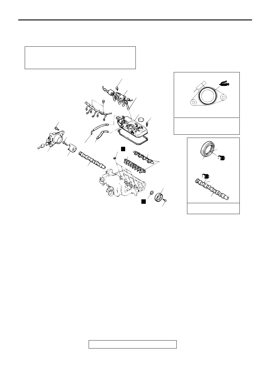
CAMSHAFT REMOVAL STEPS
1.
SPARK PLUG CABLE
2.
IGNITION COIL
3.
PCV HOSE
4.
BREATHER HOSE
5.
ROCKER COVER
6.
CAMSHAFT POSITION SENSOR
SUPPORT
7.
CAMSHAFT POSITION
SENSING CYLINDER
<<A>>
>>C<<
8.
CAMSHAFT SPROCKET
10. SPARK PLUG GUIDE OIL SEAL
<<B>>
>>A<<
11. ROCKER ARM AND SHAFT
ASSEMBLY (INTAKE SIDE)
<<B>>
>>A<<
12. ROCKER ARM AND SHAFT
ASSEMBLY (EXHAUST SIDE)
13. CAMSHAFT
CAMSHAFT OIL SEAL
REMOVAL STEPS
<<A>>
>>C<<
8.
CAMSHAFT SPROCKET
>>B<<
9.
CAMSHAFT OIL SEAL
CAMSHAFT REMOVAL STEPS
CAMSHAFT AND CAMSHAFT OIL SEAL
TSB Revision
ENGINE MECHANICAL <2.4L ENGINE>
11A-18
REMOVAL SERVICE POINTS
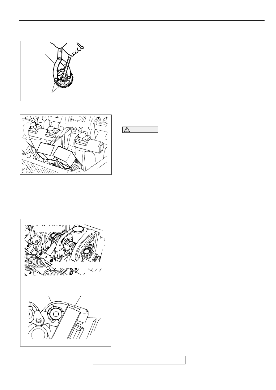
<<A>> CAMSHAFT SPROCKET REMOVAL
1. Use special tools MB990767 and MD998719 to loosen the
camshaft sprocket securing bolt.
2. Remove the camshaft sprocket.
<<B>> ROCKER ARM AND SHAFT ASSEMBLY REMOVAL
1. Install special tool MD998443 as shown in the illustration so
that the lash adjusters will not fall out.
CAUTION
Never disassemble the rocker arm and shaft assembly.
2. Loosen the rocker arm and shaft assembly mounting bolt,
and then remove the rocker arm and shaft assembly with the
bolt still attached.
INSTALLATION SERVICE POINTS
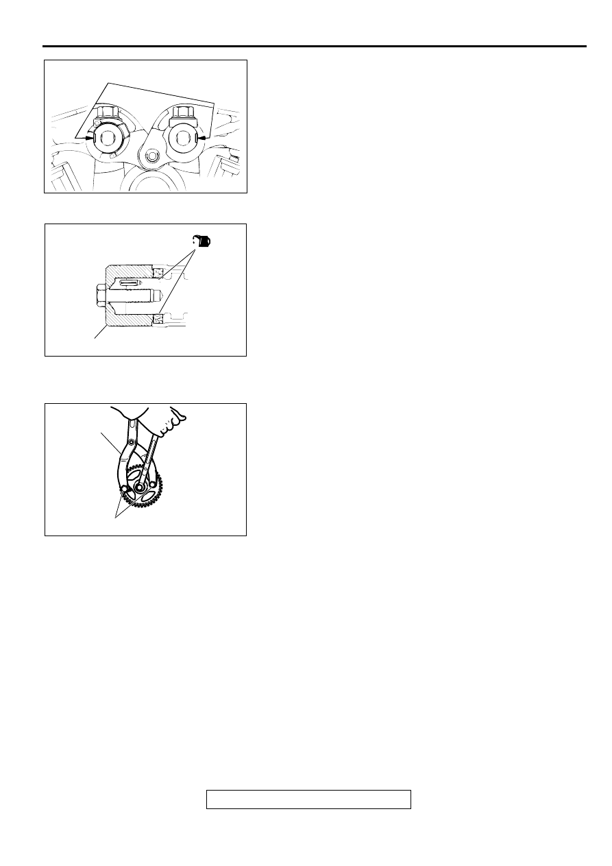
>>A<< ROCKER ARM AND SHAFT ASSEMBLY
INSTALLATION
1. Temporarily tighten the rocker shaft with the bolt so that all
rocker arms do not push the valves.
2. Fit the rocker shaft spring from the above and position it so
that it is right angles to the plug guide.
NOTE: Install the rocker shaft spring before installing the
rocker arm and rocker arm shaft on the exhaust side.
3. Tighten the rocker arm and shaft assembly mounting bolt to
the specified torque.
Tightening torque: 31
±
3 N
⋅
m (23
±
2 ft-lb)
4. Remove special tool MD998443.
ACX00301AB
MB990767
MD998715
ACX00331AB
MB998443
ACX00378
PLUG GUIDE
ROCKER SHAFT SPRING
ROCKER SHAFT
SPRING
PLUG GUIDE
AB
CAMSHAFT AND CAMSHAFT OIL SEAL
TSB Revision
ENGINE MECHANICAL <2.4L ENGINE>
11A-19
5. Make sure that the notch in the end of the rocker arm shaft
is facing the direction shown.
>>B<< CAMSHAFT OIL SEAL INSTALLATION
1. Apply engine oil to the camshaft oil seal lip.
2. Use special tool MD998713 to press-fit the camshaft oil
seal.
>>C<< CAMSHAFT SPROCKET INSTALLATION
1. Install the camshaft sprocket.
2. Use special tools MB990767 and MD998719 to tighten the
camshaft sprocket securing bolt to the specified torque.
Tightening torque: 88
±
10 N
⋅
m (65
±
7 ft-lb)
AC000131
NOTCH
AB
ACX00372 AB
MD998713
<RIGHT BANK>
ACX00301AB
MB990767
MD998715
OIL PAN
TSB Revision
ENGINE MECHANICAL <2.4L ENGINE>
11A-20
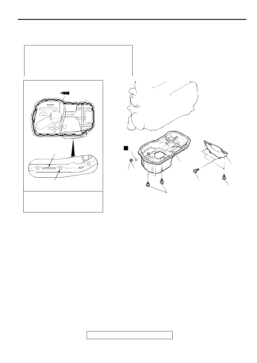
O IL PA N
REMOVAL AND INSTALLATION
M1112002800116
Required Special Tool:
•
MD998727: Oil Pan Remover
Pre-removal and Post-installation Operation
•
Engine Oil Draining and Refilling (Refer to GROUP 12,
On-vehicle Service
−
Engine Oil Replacement
.)
•
Oil Dipstick Removal and Installation
•
Front Exhaust Pipe Removal and Installation (Refer to
GROUP 15, Exhaust Pipe and Main Muffler
.)
AC000132
SEALANT:
MITSUBISHI GENUINE PART
NO.MD970389 OR EQUIVALENT
Ø 4 mm
(0.2 in)
GROOVE
BOLT HOLE
1
4
3
N
2
39 ± 5 N·m
29 ± 4 ft-lb
6.9 ± 0.9 N·m
61 ± 8 in-lb
26 ± 4 N·m
19 ± 3 ft-lb
8.8 ± 1.0 N·m
78 ± 9 in-lb
AB
REMOVAL STEPS
1.
DRAIN PLUG
>>B<<
2.
DRAIN PLUG GASKET
3.
BELL HOUSING COVER
<<A>>
>>A<<
4.
OIL PAN
REMOVAL STEPS (Continued)
Нет комментариевНе стесняйтесь поделиться с нами вашим ценным мнением.
Текст