Mitsubishi Eclipse / Eclipse Spyder (2000-2002). Service and repair manual — part 159
MULTIPORT FUEL INJECTION (MFI) DIAGNOSIS
TSB Revision
MULTIPORT FUEL INJECTION (MFI) <2.4L ENGINE>
13A-335
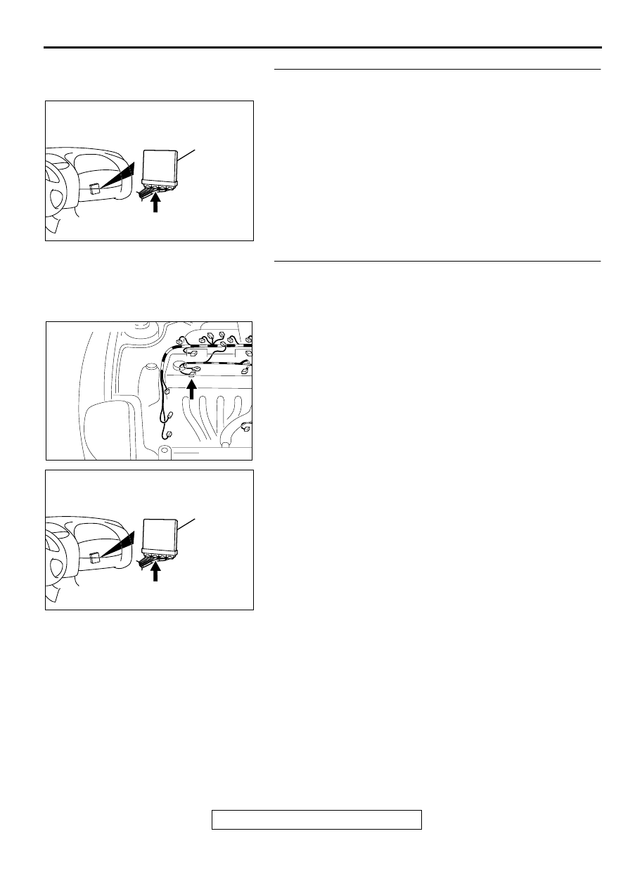
STEP 7. Check connector C-53 at ECM <M/T> or connector
C-54 at PCM <A/T> for damage.
Q: Is the connector in good condition?
YES : Go to Step 8.
NO : Repair or replace it. Refer to GROUP 00E, Harness
Connector Inspection (
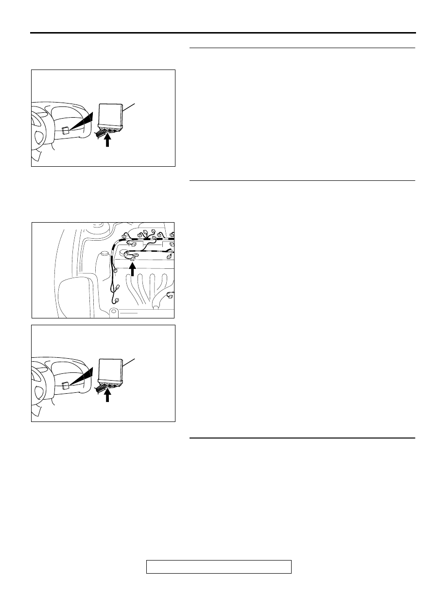
STEP 8. Check for open circuit and short circuit to ground
between generator connector B-45 terminal 4 and ECM
connector C-53 terminal 41 <M/T> or PCM connector C-54
terminal 54 <A/T>.
Q: Is the harness wire in good condition?
YES : Replace the ECM or PCM. Then go to Step 11.
NO : Repair it. Then go to Step 11.
AK000280
C-53,C-54
ECM<M/T>
OR
PCM<A/T>
CONNECTORS:C-53<M/T>,C-54<A/T>
BH
AK000546AC
CONNECTOR:C-45
AK000280
C-53,C-54
ECM<M/T>
OR
PCM<A/T>
CONNECTORS:C-53<M/T>,C-54<A/T>
BH
MULTIPORT FUEL INJECTION (MFI) DIAGNOSIS
TSB Revision
MULTIPORT FUEL INJECTION (MFI) <2.4L ENGINE>
13A-336
STEP 9. Check connector C-53 at ECM <M/T> or connector
C-54 at PCM <A/T> for damage.
Q: Is the connector in good condition?
YES : Go to Step 10.
NO : Repair or replace it. Refer to GROUP 00E, Harness
Connector Inspection (
STEP 10. Check for harness damage between generator
connector B-45 terminal 4 and ECM connector C-53
terminal 41 <M/T> or PCM connector C-54 terminal 54 <A/
T>.
Q: Is the harness wire in good condition?
YES : Replace the generator. Then go to Step 11.
NO : Repair it. Then go to Step 11.
STEP 11. Test the OBD-II drive cycle.
(1) Carry out a test drive with the drive cycle pattern. Refer to,
Procedure 6
−
Other Monitor (
).
(2) Check the diagnostic trouble code (DTC).
Q: Is the DTC P1500 is output?
YES : Retry the troubleshooting.
NO : The inspection is complete.
AK000280
C-53,C-54
ECM<M/T>
OR
PCM<A/T>
CONNECTORS:C-53<M/T>,C-54<A/T>
BH
AK000546AC
CONNECTOR:C-45
AK000280
C-53,C-54
ECM<M/T>
OR
PCM<A/T>
CONNECTORS:C-53<M/T>,C-54<A/T>
BH
MULTIPORT FUEL INJECTION (MFI) DIAGNOSIS
TSB Revision
MULTIPORT FUEL INJECTION (MFI) <2.4L ENGINE>
13A-337
DTC P1610: Immobilizer Malfunction
TECHNICAL DESCRIPTION
•
ECM <M/T> or PCM <A/T> monitors the
communication condition with the immobilizer-
ECU and the message from the immobilizer-
ECU, and when the abnormality is found, ECM
<M/T> or PCM <A/T> makes the engine not to
start.
DTC SET CONDITIONS
Check Conditions
•
Ignition switch: ON
Judgment Criteria
•
When the communication error between ECM
<M/T> or PCM <A/T> and the immobilizer-ECU
continues for 2 seconds or more.
•
When ECM <M/T> or PCM <A/T> receives the
communication of prohibition for starting from the
immobilizer-ECU.
TROUBLESHOOTING HINTS (The most likely
causes for this code to be set are:)
•
Malfunction of harness or connector.
•
Malfunction of immobilizer-ECU.
•
Malfunction of ECM <M/T> or PCM <A/T>.
DIAGNOSIS
Required Special Tools
MB991502: Scan Tool (MUT-II)
CAUTION
To prevent damage to scan tool MB991502, always turn the
ignition switch to the "LOCK" (OFF) position before
connecting or disconnecting scan tool MB991502.
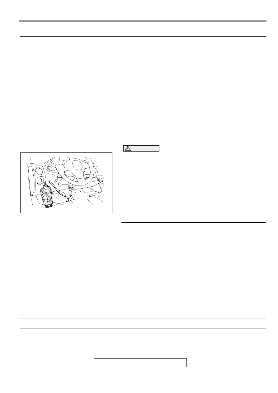
STEP 1. Using scan tool MB991502, read the immobilizer
diagnostic trouble code (DTC).
(1) Connect scan tool MB991502 to the data link connector.
(2) Turn the ignition switch to the "ON" position.
(3) Read the immobilizer system-DTC
(4) Turn the ignition switch to the "LOCK" (OFF) position.
Q: Is the immobilizer system-DTC is output?
YES : Refer to GROUP 54A, Ignition Switch and
Immobilizer System
−
Diagnostic Trouble Code Chart
NO : If DTC P1610 is output again after the MFI-DTC has
been erased, replace the ECM <M/T> or PCM <A/T>.
Then check that the DTC P1610 does not reset.
DTC P1751: A/T Control Relay Malfunction
TECHNICAL DESCRIPTION
•
When a malfunction of the A/T control relay is
detected, the transaxle control CPU inside the
powertrain control module (PCM) outputs a
malfunction signal to the engine control CPU
inside the PCM.
AKX01177
16 PIN
MB991502
AB
MULTIPORT FUEL INJECTION (MFI) DIAGNOSIS
TSB Revision
MULTIPORT FUEL INJECTION (MFI) <2.4L ENGINE>
13A-338
DTC SET CONDITIONS
Check Conditions, Judgment Criteria
•
A/T control relay failure signal is input to the
engine control CPU from the transaxle control
CPU.
TROUBLESHOOTING HINTS (The most likely
causes for this code to be set are:)
•
A/T control relay failed.
•
Open or shorted A/T control relay circuit, or loose
connector.
•
PCM failed.
DIAGNOSIS
Required Special Tools
MB991502: Scan Tool (MUT-II)
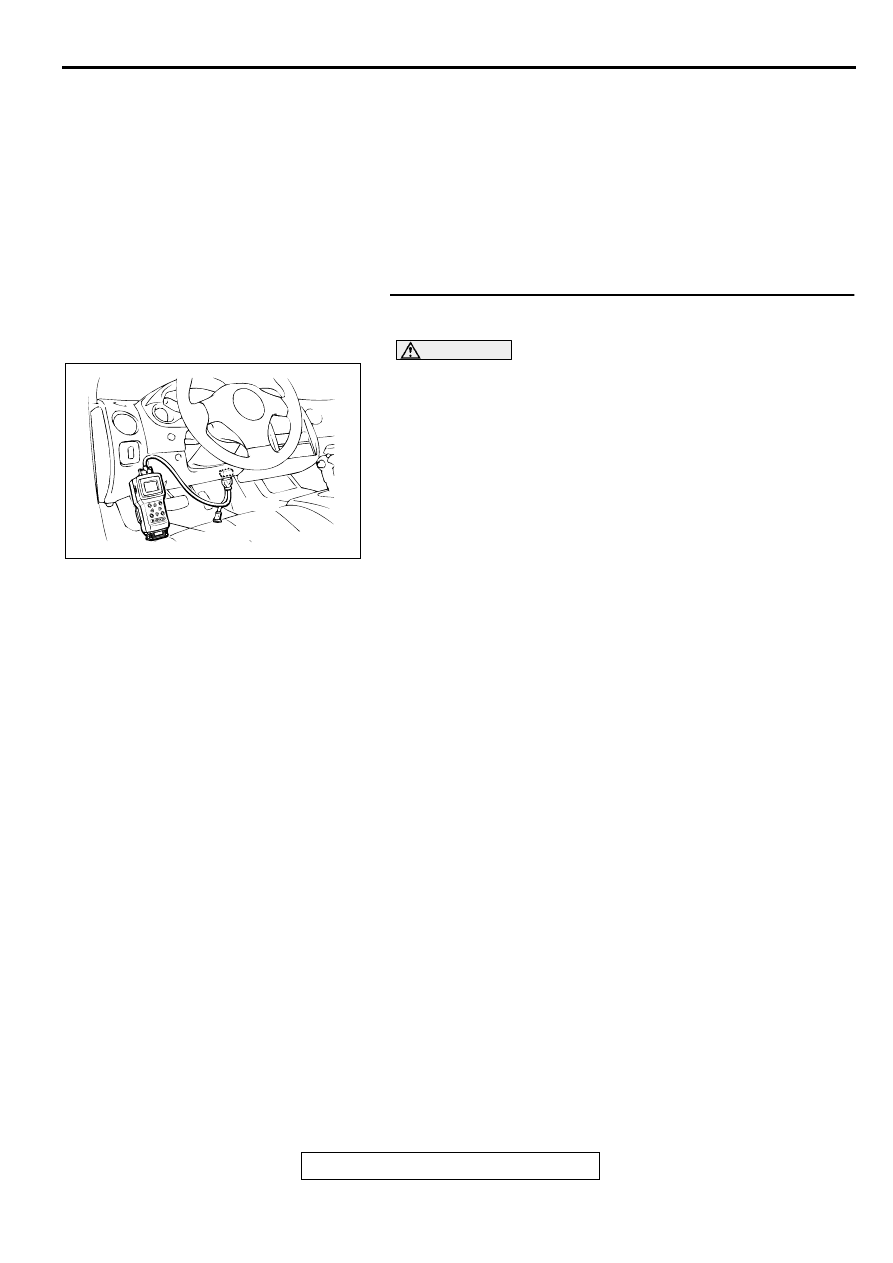
STEP 1. Using scan tool MB991502, read the A/T
diagnostic trouble code (DTC).
CAUTION
To prevent damage to scan tool MB991502, always turn the
ignition switch to the "LOCK" (OFF) position before
connecting or disconnecting scan tool MB991502.
(1) Connect scan tool MB991502 to the data link connector.
(2) Turn the ignition switch to the "ON" position.
(3) Check the A/T-DTC.
(4) Turn the ignition switch to the "LOCK" (OFF) position.
Q: Is the A/T-DTC is output?
YES : Refer to GROUP 23A, Automatic Transaxle
Diagnosis
−
Diagnostic Trouble Code Chart (
NO : If DTC P1751 is output again after the MFI-DTC has
been erased, replace the PCM. Then check that the
DTC P1751 does not reset.
AKX01177
16 PIN
MB991502
AB
Нет комментариевНе стесняйтесь поделиться с нами вашим ценным мнением.
Текст